Re: Hi lineup.
I have no doubt a real life circuit would have less pefect data.
But simulations give a hint,
what is a
- very good circuit,
- good or
- less good or
- poor or
- not working
Comparing to other OP-amp circuits I love and have simulated
this one is Top Of My Top, so far!!!
.... and I have set up like 10-20 different clones and also my own ideas.
------------------
I know AD797 has more in the INPUT than a single pair normal Q.
We can only set input bias current in relation to Current in input pair
to see this.
What they say is, they use special high beta input transistors.
But those are not for me.
And as it is a very simplified diagram Analog Devices has published,
each stage probably have a lot more improvements details!
------------------
Better schematics OPA 646_ ????????
If there is some better schematic of the AD797 circuit
I am interested - VERY INTERESTED 😎 😎
Regards and
Chrsitmas
lineup
hastros said:
AD797 in input 12+12 transistors::::: LOW NOISE tech.
Better schematics OPA 646_?
I have no doubt a real life circuit would have less pefect data.
But simulations give a hint,
what is a
- very good circuit,
- good or
- less good or
- poor or
- not working
Comparing to other OP-amp circuits I love and have simulated
this one is Top Of My Top, so far!!!
.... and I have set up like 10-20 different clones and also my own ideas.
------------------
I know AD797 has more in the INPUT than a single pair normal Q.
We can only set input bias current in relation to Current in input pair
to see this.
What they say is, they use special high beta input transistors.
But those are not for me.
And as it is a very simplified diagram Analog Devices has published,
each stage probably have a lot more improvements details!
------------------
Better schematics OPA 646_ ????????
If there is some better schematic of the AD797 circuit
I am interested - VERY INTERESTED 😎 😎
Regards and
Chrsitmas
lineup

QSerraTico_Tico said:the current mirror is crucial
YES!
It is a FLOATING current mirror. .. follows level of output voltage.
It is not attached to V-, like we do it,
but it is biased by a CCS current source (I7) from negative.
😎 The real trick is Q12. 😎
Without this important transistor
( taking care of current variations, left-overs of currents )
it wouldn't work.
Regards & Christmas
lineup
Lineup Audio Lab
http://lineup.awardspace.com/
Attachments

Lineup, you really need to put emitter resistors in the output stage. The AD797circuit you’ve copied uses the “Diamond Buffer” circuit as an output stage without any emitter resistors. This is fine for a circuit made on an IC chip, as the driver and output transistors can be closely matched and thermally bonded.
If you were to build the circuit with discrete transistors, the first time you apply power, the output transistors will either turn on hard and blow up almost straight away, or thermally runaway and blow up a few seconds later.
Cheers,
Glen
If you were to build the circuit with discrete transistors, the first time you apply power, the output transistors will either turn on hard and blow up almost straight away, or thermally runaway and blow up a few seconds later.
Cheers,
Glen
Hi Gk,
is that what happens to the diamond buffer?
One transistor hogs the output current? and then overheats?
is that what happens to the diamond buffer?
One transistor hogs the output current? and then overheats?
AndrewT said:Hi Gk,
is that what happens to the diamond buffer?
One transistor hogs the output current? and then overheats?
Generally not. Both the NPN and PNP will be biased on and will draw equal current unless the output voltage isn't at 0 volts and there is some current flowing into the load. Without emitter resistors they will just thermally runaway and quickly blow up.
How quickly they blow all depends on how heavily they are biased on when power is first applied, and that depends entirely on how much current is being sunk/sourced to/from the pair of driver transistors.
Cheers,
Glen
G.Kleinschmidt said:Lineup, you really need to put emitter resistors in the output stage. The AD797circuit you’ve copied uses the “Diamond Buffer” circuit as an output stage without any emitter resistors.
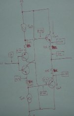
If you have a look at my Later own version, based on AD797 topology,
but some changed and added features:
High Voltage Op-amp (100Volt or +/-50V)
using 2SK373 JFETs input (minimum input bias current = offset precision)
and 2N5551 + 2N5401 transistors for the Diamond
....you will notice
I have used small emitter resistors, for better control of idle current in output.
SEE My Attachment - second time around! .... wont be a third opportunity 😉
*****************************************************
But the initial test circuit, built very much to explore AD797
uses no such emitter resistances, and simulates well enough,
as Electronics WorkBench, EWB MultiSim9, assume ideal perfect match transistors.
Lineup Introduction Post = Post #1 of this thread:
My circuit is in attachment and follows the AD797 schematic
- what I know from reading This Datasheet Very Closely
---------------------
All transistors BC550C and BC560C.
Total Supply Current 8.0 mA
Output stage, like the original biased only 0.5 mA ( 492uA more precise .... )
Regards to G.Klein
- who has to study more
the circuits of Lineup Audio Lab
lineup 😎 chief designer of Lineup Audio
😎 often a step ahead of the crowd
... and many times right and some times wrong
Attachments

lineup said:
Regards to G.Klein
- who has to study more
the circuits of Lineup Audio Lab
lineup 😎 chief designer of Lineup Audio
😎 often a step ahead of the crowd
... and many times right and some times wrong
D'oh.....OK
To be fair though, you didn't mention the emitter resistor change in your text, so I didn't bother clicking on your image 🙂
Anyway, have you considered adding emitter resistors to the driver transistors as well? I’ve just draw a simplified circuit of how I like to make discrete diamond buffers. In order to have a predictable output stage bias current, I use emitter resistors for both the driver and output transistors.
The diagram I’ve scribbled shows a design for an output stage with 10mA quiescent bias current. The output transistor bias current is roughly equal to the driver transistor emitter resistor to output transistor emitter resistor ratio times the driver bias current. In this case, 20R/10R*5mA = 10mA.
Note that this is a simplified description, as a 700mV Vbe is assumed for all transistors. In reality, the actual output transistor bias current will generally be slightly greater than calculated in this manner, as the output transistors, running at greater current and higher junction temperature, will run with a lower Vbe than the driver transistors.
Cheers,
Glen
Attachments
I ask again.
Where is this schematic that Lineup offers for the second time?
Where is this schematic that Lineup offers for the second time?
SEE My Attachment - second time around! .... wont be a third opportunity
lineup said:
lineup 😎 chief designer of Lineup Audio
😎 often a step ahead of the crowd
... and many times right and some times wrong
😀 😀 😀
Great work lineup.
If you should boost the supply voltage to +/- 30-40V, make thermal compensation and the right output devices, would this poweramp then beat the sym-a-sym?
If you should boost the supply voltage to +/- 30-40V, make thermal compensation and the right output devices, would this poweramp then beat the sym-a-sym?
AndrewT said:I ask again.
Where is this schematic that Lineup offers for the second time?
Thanks for interest AndrewT.
At least you have the good taste of NOT trying make fun of me.
Not all can stop themselves from talking negatives
and keeping non constructive opinions within their own brain Only.

I never forget what is done to me,
but I might chose to not give it any greater public notice
and just ignore all hasty comments thrown at me.
I very seldom reports to moderators all foolishness seen.
It is better it stays in topic .. their bad words will for ever bear witness about these individuals.
😎
As they say:
1. By the fruit of the tree we know the tree.
2. A bad tree gives bad fruit. It will be cut, it is good for nothing. But to burn.
3. A good tree gives you good fruit. It will live forever. In My Kingdom of Trees.
😎
Most information I have given away, so far
is in Post #6 here above.
http://www.diyaudio.com/forums/showthread.php?postid=1087124#post1087124
So you haven't missed more than anybody else.
Like somebody said:
The real benefit of using discrete clones of Op-Amps
is when we add some features that such High Performance Chips
CAN NOT deliver.
Like very high supply voltages = high voltage input/output.
This fact, though, does not mean we can not / should not learn from
and use some same topologies and elements
that makes these good op-amp chips so good.
So ... this is what I did .. and still do
... many other op-amp versions have been created and evaluated in my Sims.
--------------------------------------
Right now, today,
I am working with with another more basic op-amp / preamp design
that has not been so much explored.
I haven't seen it just. about nowhere.
Except for one guy at one website!!!!!
I think he (and I) might be on to something useful ... 😉 for audio amps.
Also.
I find it very interesting to setup circuits, using just about same criterias
but with different input pair solutions and configurations
... then have a look at Fourier Harmonics spectrum.
Sure is the input stage of op-amp style amplifiers, with global feedback,
is very much involved in the finer points, fingerprint
of such circuits!
At least my Fourier testing tells me so.
-----------------------------------
I know from my own practical setups and experiments, for example,
that the one often told difficulty of making good thermal matching and compensation
when using discrete devices,
is over rated.
If you do it properly, which often is done in hihi power amplifiers
you will get a discrete op-amp with very low drift caused by temperature.
That is the within normal houses environment.
And should there be small such drifting
it wont effect your final audio sound waves outputs
most anything at all.
So I would say the advantage here, by all commonly used op-amps
is nothing to really worry about and certainly very much overrated
and overstated by critical persons having little or no practical experience of this.
Discrete op-amps
with their possibility to customly set currents and voltages
as well as select suitable transistors for each job
is not only more fun - it will by a good transistor diy person
get close to maximal good audio data and final results.
Those interested in only IC Op-amps
does not have to bother with topics like this.
They can go to Chip Amps forum.
... an meet me there too
... Chip Amp people, I have found, are often very nice to deal with
😉
I am sure there are some good other places to go
also for them being only critical to what is presented to them.
Because is not always very constructive to have them around your neck.
christmas
lineup 🙂 trying to be nice but evenso honest ... for good or bad
just a thought......
most good power amp designs are basically discrete op amps made big.
unfortunately "simplified" op amp schematics are somewhat oversimplified. many of the "resistors" and "caps" are forward or reverse biased transistor junctions. all of the transistors are perfectly balanced, because they are on the same silicon die.
if you build a simulation, try designing a bit of randomness into the component values and active components, to get a taste of the "real world" into the sim results. remember, most of your real world resistors have 5% tolerance, transistor betas can vary as much as 100% (look at a transistor data sheet, where it says "beta 150 typ, 300 max), ceramic caps have 10% tolerance, and electrolytics are +20%/- 10%. you might just want to go through that "perfect design" after getting it right, and starting with all of the resistors in numeric order roll dice, one die is for even/odd=+/-, and the other die is for how many percent (use 6 for no change). adjust the betas on some of your transistors. after adjusting your parts values in this way, see if your distortion measurements have changed.
the only alternative is to carefully test and match every transistor and use 1% resistors for everything which is time consuming and expensive.
lineup said:[snip]Regards to G.Klein
- who has to study more
the circuits of Lineup Audio Lab
[snip]
There are no circuits in your audio lab site.
Jan Didden
For someone whose first post said:
I am not sure anyone could do this better than myself
maybe get some similar results, but not better, I doubt.
and other, similar chest-pounding statements, I can't say that I'm surprised at the self-pitying tone the thread has taken.
Don't get me wrong, opamps are fine in their place, simulations can be interesting, and reasonable discussions of circuit topology can definitely be educational. Unfortunately, this thread has all the wrong proportions of all the wrong ingredients. Too much ego. Too much puffery. Too little discussion of what aspects of the topology contribute to the performance of the '797.
And way, way too many exclamation points!!!!!!
Not to mention needless overuse of colored typefaces and other LOOK AT ME attention-getting ploys.
Granted, it's a personal decision as to how much of this sort of thing to put into a post, but I think most people would agree that this thread looks more like it was composed by a carnival barker than someone wanting to make a serious (or even semi-serious) attempt to talk about the '797.
As to whether anyone can do better in a simulation...who cares? Turn off the computer and turn on the soldering iron. When you have a functioning discrete circuit that approaches the breathless claims made in the first few posts, then by all means shout them from the rooftop.
Until that time, it should come as no surprise that others prefer nitty-gritty reality to cotton candy fantasies. Crying because others do not share your enthusiasm for empty parlor tricks does no good.
Grey
thanh said:Hi ! I'm still interested in low THD opamp 🙂
The schematic run in Orcad but It has 11V offset voltage in LTspice.
I don't know whether I drawn wrongly
Thanh, polarity of V2 (minus supply) is wrong,
Heinz!
Rather than tilting at windmills (another term for trying to clone an opamp with discrete components), try something more useful. A discrete opamp with capabilities a an IC opamp doesn't have.
Ability to run off higher voltage (+/-50V) rails.
Ability drive low impedance loads.
Ability to perform well with unregulated supplies.
Build the above in relatively compact package using all/mostly SMT components with some sort of inline edge connector that lets it be soldered or plugged in to a main board.
By the way, 2n5551 and 2n5401 (as well as some other common discretes often used in audio) can each be found in in matched pairs in SMT packages -- this alone should get someone thinking about possibilities.
- Home
- Amplifiers
- Solid State
- AD797 Clone people! Who can make a better one.