Yes, like this.
For example: for 10ohm i/v input impedance and +-1mA current out, the voltage will swing only +-10mV which is nowhere near the forward voltage of the diodes. So they don´t conduct and should definitely be used at least while the dac is being tested.
In case you made some mistake during your build / had a failure on the i/v / your probe slipped while measuring / etc... Then the diodes are there to limit the voltage +-0.6v and save your dac chip. Better be safe than sorry!
Thanks Alexandre,
Is not one a noise generator as Zener Active device, even if signal diode ? If none conduct = no noise ?
Last edited:
OSH Park ~ Welcome
What is the most easy & economic way to share design without buying an expensive Eagle software for one shot design for enthusiasts (when the time for collaborative comes like the moment to print it)?
EasyEDA - Web-Based EDA, schematic capture, spice circuit simulation and PCB layout Online : here a link given by a fellow...
EasyEDA offer a low cost PCB manufacturing service too: that's where they make their money rather than charging for the tool. It looks like their prices may be even lower than OSH Park even after you add shipping. You're not tied to them because you can download the Gerbers for an EasyEDA PCB and take them anywhere you like but it would be worth looking at:
EasyEDA PCB fabrication prices / capabilities EasyEDA
🙂
Eldam,
Let me think... 20 bits = 2^16 levels = 1048576 levels.
With ad1862 we have 2mA p-p swing, divided by the amount of levels we get the lsb current: 0.0019 uA or 2 nA. Wow, that´s a very small current. I think the diode will conduct more than 2nA and make some *very low* level noise indeed.
But please leave it there while testing!
(On the other hand, pcm63 has internal protecting diodes, and it´s claimed 20 bits, so there must be appropriate diodes for this task with a very low leakage current)
Hi Eldam, I gave my honest advice, there is something in the app notes about an analogue type plane for the switch decoupling caps, also mentions they have switching noise on them, but its an old chip and I cant find it on the internet, and my old legacy PC with a lot of info on got wiped out by a virus.
ok, i understand now : just if an error occur to avoid break at switch on.
If good after the first test, can be removed for the final device 🙂
If good after the first test, can be removed for the final device 🙂
This looks good to me at least. But don't forget the cap between pin 1 and 15.
The GND, SIG, SIG, GND stackup is the one that I opted for as well.
I thought its better to solder the cap directly to the pins of the chip, thats the reason i left it out.
Ground plane always have to be stitched together with vias, round the edges as well is always good, don't need to be so close though, and add some random ones in board, as per picture below. These help break-up any tendency for resonant waves to build up on the planes, more a problem with power ground pairs, but can still effect just ground planes. Stitching vias round the edge of boards (a techniques used in RF design a lot) also helps supress edge radiation of noise.
The above stackup would be great for this design as you get excellent shielding for EMC purposes. Most commercial boards tend to have a hybrid version of this, where there are a mixture of tracks and copper pour on the top, as it limits the number of PTH vias, which can be problematic from a cost and spacing point of view.
HDI PCB designs though, that I do more and more of these days this is coming back into fashion as the vias are laser drilled and only pass through one layer so you don't block inner layer routing directions, also the cost doesn't go up when you start getting into the few thousand vias on a board. We have many a merry discussion on the various board stack-ups that are available for a particular design as there are advantages and problems with all choices. There are so many factors at play it can be quite fun (if you are into PCBs to the same SAD extent I am).
One area where todays high speed boards differ is power planes will have a closely coupled ground planes (both are done as planes, the power is not routed as tracks unless the design is very simple) to give buried capacitance.
http://www.ddmconsulting.com/Design_Guides/bcguide.pdf
Decoupling this is OTT for this design but usefull knowledge as you go on to more complex designs.
No you need the low value 0.1uF next to the pin, for the high frequency decoupling it provides, the rule for the pin decoupling capacitors is actually find the smallest package available for the value chosen...
http://www.pcbcarolina.com/images/01_pcb_power_decoupling_myths_debunked.pdf
Decoupling
Decoupling
http://www.intersil.com/content/dam/Intersil/documents/an13/an1325.pdf
Had a look at the TDA1541 thread, and looking at the data sheet for said device...some thoughts, don't like the star routing much, but it is a bit of a strange device and I have seen numerous solutions, but the decoupling caps do have high frequency noise on them and as such the lowst impedance return path should be used.🙂
Sorry for OT.
Marce you have a wealth of information! 🙂 Ok time to find out how to stitch top and bottom ground plane in eagle. 😀 I'll be swapping the pin header with u.fl connectors and i'll reduce pcb thickness to 1.2mm
I've spent 28+ years laying out PCBs and designing complete electrical/electronic assemblies, so I've spent a long time studying it all and doing it...its my limited area of expertease🙂 Luckily now in the UK with the diminishing supply of experienced PCB designers I am always busy, sometime to busy.
I don't use eagle but I'll have a look on EDA forum, there's some very experienced users on there and I believe this may have come up.
In the system I use you can cut and paste vias onto the copper pour. (Cadstar)
I don't use eagle but I'll have a look on EDA forum, there's some very experienced users on there and I believe this may have come up.
In the system I use you can cut and paste vias onto the copper pour. (Cadstar)
Pffffffffffff Marce, 28 years is nothing, I am 45 and I listen crap hifi from my 15 years old and always with second hand devices 😉😀
Ask someone to tell you HERE if in the absolute: tubes are better than solidstates, modern chips better than R2R dac, high efficienty better than low for distorsions or approach the real dynamic : Silence or battles, it stays politics and the ones who spend money all their life will never respond to those questions : I tried when I join DIYA 2 years ago !
More seriously, if there were more people like you for sharing their great experience with experienced diyers which are more involved by audio than industrial electronic (and knows where the technics can be less musical than electrical efficienty design on the paper), diyers waste less time. That's why it's great when you share more didactic than direct answer with your links. Old two cents diyers like me knows two or three things about caps (more about subjective musicality by experience than technical spec), sometimes great spec do not avoid to have bad sound and some mix are worst than others...scopes see manythings but are not able to see all, mainly because IHMO we need to go further with measurements (more than ten harmonics in the analog stages and not only 3 or five like we see most of time !). People like T. Loesch or P Rodric who share the two worlds has great sucess to make musical devices...there are not alone, but most of the good brands are far most expensive for our too much fanatic needs
Hi Painkiller ,
Sorry totaly OT here & much too long... how to be forgived here 🙁 ! Ah, maybe a little add : 1862 is greater than PM63 at bass frequency -more bass like the actual Wolfson- but more odd harmonics in high... but of course in the absolute. Layout around is IHMO more important when you benchmark the both chip). I will be happy to have your review when you will be able to listen to it with the final set up in relation to th elittle 18 bits brother : aka stereo AD1865. Unfornatly, I found a chineese vendor hifi-szjxic on EBAY : 8 dollars the AD1862 chip... but impossible to know if they are genuine and non double CMOS copy !)... This is not DIGCHIP with genuine certificate !
Last edited:
Eldan, I have spent 28 years designing PCBs, I wish I was 28, instead 0f 53😀
I have 15 year old twins (they are the youngest of our brood )
)
To save arguments in our house we have a SS and a Tube system, though I do need some new speakers...soon.
I have 15 year old twins (they are the youngest of our brood
)To save arguments in our house we have a SS and a Tube system, though I do need some new speakers...soon.
Last edited:
Yes Marce i understood fine, it was to say for me it was no 28 years of RF but 30 years of hearing bad system at home ! It's a real job to suffer 30 years of bad hifi 😀 ( so I joke because had good luck with speakers, less with the rest... hard to marry devices on the second hand markett)
One pair of speaker per Child 😉
Disaster we are total Off Topic
One pair of speaker per Child 😉
Disaster we are total Off Topic
Some off topic discussion is of course welcome, as long as it's not unfriendly. 🙂
It's great to be able to get advice from both experienced professionals like marce and the eager diy'ers. I do believe this thread has been very productive and informative. At least for me. Success lies in the intersection between theory and practice.
I too bought some chips from hifi-szjxic. They did work. But can they be fake? I also have some from another e-bay seller bbshonic. They were more expensive. Also working chips.
I think I have to send a couple boards to production soon, so the project doesn't end up on the drawing table. Then I can start soldering, trying out different caps etc. If I end up making changes to the layout, like making a stereo board, or switching to a different output stage, I can just run another batch.
I've changed the SMD footprints to 0603, for the 100nF x7r caps. And also made room for Rhopoint I/V resistor. Originally it was fit for RN55 resistors.
I am a poor diyer, more a tweaker in fact but Marce and Peufeu have real knowledge and understanding of both electrical and digital environments.
I liked your thread because you start almost from scratch with verroboard...with lake of pretension. We are trying to do that in an another thread with the TDA1541 and there are often bad willed people who are staying on the side of the non action but critize all the times instead helping with what they have (hypocrites in my dictionnary🙁 ) and by the way sometimes dialoguers need to become less friendly... that's life, nothing wrong it's not the war afterall. But we saw than few good willed people can do a cool job, the more they are the better and the faster. Merging ideas and sharing hints fight a little against the lake of knowledge for enthusiasts like us and sometimes we can have a great help from our more professional friends like marce e.g. is in real life with him job (and share after it with his free time). Is sharing not the goal of such forums 🙂... And voila, I come back to the side of bad litterature (in fact it's hard to write short and share idea when you can not master the language like me here, sorry for that).
It's a cool project here according my own idea of DIY audio and give me the desire to test more with these 20 bits mono chips in relation to the little stereo AD1865 18 bits... I think the harder is to find good genuine pcm63 or AD1862/5. You can with Digchip or another one company i forgiv the name but you must buy 5 or ten of eachs : means GB and the price is equal to the genuine guaranty : around 50 dollars the chip !
I really don't know if those South Asia vendors sell fake chip. Maybe urban legend ! After all it's maybe more expensive to produce fake than find new old stock ?! Is it expensive to produce again a chip from scratch ? i assume just the genuine suppliers factories are able to do that but without the permission of the customer brands: Analog device, Burr Brown... So maybe true chips but unauthorised production ? We need testimonies about that and i never be able to read audiophiles who measures those chips in relation to a say a genuine one tooked from a genuine CD player/DAC! But maybe some guys with the TDA 1541... and they found there were great differences between chips and years of production also : laser treaming, etc...
Most of the time they mark low grad chips with high grad marks to raise the price.
You can find the Rhopoint Z foil double wirewound resistor in bulk (said to be better, resisitors are green and are used byT Loesch or ECDESIGNS in their best designs) or in smd z foil packahe at Vishay precision group (owner of Rhopoint).
I hope stacking the boards will work for you with multiple vias in the gnd layers.
To connect the both gnd layers, maybe you can use also the Peufeu plugs for that to be able to work after on the boards and try diferent positions for the less noisy without soldering (e.g; reverse one of the board for best matching the pins in a vertical mirror configuration (top of the two chips close togethers like with a mirror !). You can maybe use this to connect the both stacked boards for your tests : Connecteurs circuit imprimé - Réglette sécable à broches 1X36 écartement 2.54mm. But is ist electrical RF proof... only people like Marce can say ! Just an idea to save time and brain haches with tests for you.
My belief is it will be easier to test all these conf and caps/resistors devices with plugs with your good quality verroboard you showed before print a more expensive clean board.
You can find also in the digital thread like the digital line thread good adress to print if you have none.
Just two cents.
I would be happy to have your testimonies about the sound then the differences between a verroaboard and a cleaner post production board after (do ears are able to listen to differences is an old question for me).
regards
I liked your thread because you start almost from scratch with verroboard...with lake of pretension. We are trying to do that in an another thread with the TDA1541 and there are often bad willed people who are staying on the side of the non action but critize all the times instead helping with what they have (hypocrites in my dictionnary🙁 ) and by the way sometimes dialoguers need to become less friendly... that's life, nothing wrong it's not the war afterall. But we saw than few good willed people can do a cool job, the more they are the better and the faster. Merging ideas and sharing hints fight a little against the lake of knowledge for enthusiasts like us and sometimes we can have a great help from our more professional friends like marce e.g. is in real life with him job (and share after it with his free time). Is sharing not the goal of such forums 🙂... And voila, I come back to the side of bad litterature
(in fact it's hard to write short and share idea when you can not master the language like me here, sorry for that).It's a cool project here according my own idea of DIY audio and give me the desire to test more with these 20 bits mono chips in relation to the little stereo AD1865 18 bits... I think the harder is to find good genuine pcm63 or AD1862/5. You can with Digchip or another one company i forgiv the name but you must buy 5 or ten of eachs : means GB and the price is equal to the genuine guaranty : around 50 dollars the chip !
I really don't know if those South Asia vendors sell fake chip. Maybe urban legend ! After all it's maybe more expensive to produce fake than find new old stock ?! Is it expensive to produce again a chip from scratch ? i assume just the genuine suppliers factories are able to do that but without the permission of the customer brands: Analog device, Burr Brown... So maybe true chips but unauthorised production ? We need testimonies about that and i never be able to read audiophiles who measures those chips in relation to a say a genuine one tooked from a genuine CD player/DAC! But maybe some guys with the TDA 1541... and they found there were great differences between chips and years of production also : laser treaming, etc...
Most of the time they mark low grad chips with high grad marks to raise the price.
You can find the Rhopoint Z foil double wirewound resistor in bulk (said to be better, resisitors are green and are used byT Loesch or ECDESIGNS in their best designs) or in smd z foil packahe at Vishay precision group (owner of Rhopoint).
I hope stacking the boards will work for you with multiple vias in the gnd layers.
To connect the both gnd layers, maybe you can use also the Peufeu plugs for that to be able to work after on the boards and try diferent positions for the less noisy without soldering (e.g; reverse one of the board for best matching the pins in a vertical mirror configuration (top of the two chips close togethers like with a mirror !). You can maybe use this to connect the both stacked boards for your tests : Connecteurs circuit imprimé - Réglette sécable à broches 1X36 écartement 2.54mm. But is ist electrical RF proof... only people like Marce can say ! Just an idea to save time and brain haches with tests for you.
My belief is it will be easier to test all these conf and caps/resistors devices with plugs with your good quality verroboard you showed before print a more expensive clean board.
You can find also in the digital thread like the digital line thread good adress to print if you have none.
Just two cents.
I would be happy to have your testimonies about the sound then the differences between a verroaboard and a cleaner post production board after (do ears are able to listen to differences is an old question for me).
regards
Last edited:
hello painkiller, I m following your thread with interest, by chance did you produce a pcb and get some sound of it ?
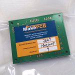
Well, yes and no. I'm waiting for a small batch of boards, on their way from China as we speak. I've sourced most of the parts. Just some Vishay Bulk Foil resistors that are missing right now (couldn't get the Rhopoints). But no sound yet.
I know it's been quiet here lately. I'm just waiting now. I've stopped testing with the veroboards as well. All the connections and the small space and everything made it difficult to work with, and not very convenient for swapping components and doing listening tests.
Eldam: Seems like you and share the same background. 🙂 It's really great to have professionals like Marce and Peufeu around. And I'm pleased to see how positive this thread has been. Everyone have been very helpful.
I do believe at least these chips are real: Ultralow Noise 20 Bit Audio DAC AD1862 - BBshonics
Well, ok, I'll give you all an update when there has been a little more progress.


super, how much did it cost to you ? You went for two boards finally !
I'm hurry to read your first listening review !
I'm hurry to read your first listening review !
Thanks! They look nice, and they feel like very high quality. But they weren't cheap. I payed $260 including shipping, for 8 boards. I ended up receiving 9. Don't know why.
I'm very eager to start soldering, but I'm buried in work right at the moment. I'll be getting back with more pics and listening impressions as soon as I can.
I'm very eager to start soldering, but I'm buried in work right at the moment. I'll be getting back with more pics and listening impressions as soon as I can.
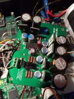
First two channels are now up and running. Attached a picture of the first card on the test bench.
Encountered some problems at first, and noticed some irritating mistakes with the board. First of all, there was an error in the silkscreen where two of the BC550/560 had been switched. Blew a couple of transistors before I found the source of the problem. Then there's not really enough space for terminal blocks. And the Belleson regulators are a bit wider than the regular LM79xx/79xx.
But it works. It really works! 😀 It is completely noise free. After adjusting the MSB trim there is no audible low level distortion. The sound is really smooth, detailed and airy. The timbre is just right. It all sounds very natural. Never harsh. Never muddy.
I think it should rather be called the Presence dac, because the music is just so natural and present.
All in all I'm very happy with the result. I think this dac really has potential, with only some minor changes is layout and component values.
Attachments
- Home
- Source & Line
- Digital Line Level
- AD1862 PCB layout