Yes, it's pretty annoying to have lost all the files. Not really motivated to start from scratch again. 😡
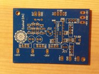
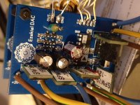
Here are a couple photos. One of the (dusty) unpopulated dac. And one of the populated prototype. It's really compact. I'm surprised at how good it sounds compared to how messy it looks 😀
Here are a couple photos. One of the (dusty) unpopulated dac. And one of the populated prototype. It's really compact. I'm surprised at how good it sounds compared to how messy it looks 😀
Attachments
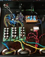
...aaand here's the finished dac in its enclosure. All is diy except the I2SoverUSB receiver. Very happy with the result!!
I haven't heard many different dacs in my setup, but I can definitely say that it's way way better than the Chord Hugo 2 and the Naim DAC, both priced at $2000 USD. Would be interesting to compare it to some higher end dacs.
I haven't heard many different dacs in my setup, but I can definitely say that it's way way better than the Chord Hugo 2 and the Naim DAC, both priced at $2000 USD. Would be interesting to compare it to some higher end dacs.
Attachments

Nice work. I saw on previous photos that you were using vishay var on riv. What is now your new resistor in use?Yes, it's pretty annoying to have lost all the files. Not really motivated to start from scratch again. 😡
Here are a couple photos. One of the (dusty) unpopulated dac. And one of the populated prototype. It's really compact. I'm surprised at how good it sounds compared to how messy it looks 😀
Nice work. I saw on previous photos that you were using vishay var on riv. What is now your new resistor in use?
Thanks! 🙂
I ended up with the Rhopoint 5G10 resistor. It's great. The value is 350R right now, because I have such efficient speakers and a high gain transistor amp.
General Resistance 5G10 Mini-Ohm Series | Rhopoint Components
Thanks for sharing, Painkiller,Thanks! 🙂
I ended up with the Rhopoint 5G10 resistor. It's great. The value is 350R right now, because I have such efficient speakers and a high gain transistor amp.
General Resistance 5G10 Mini-Ohm Series | Rhopoint Components
Your work is great inspiration, i never heard ad1862.. i will try it for sure.
Hello Painkiller,
Nice to hear from you. About R I/V, is there a big différence with the RhoRho 816G 1000R I sent you ;
I suceeded to put ufl- plugs on the previous design, you should keep the 3 x ground with the I2S inputs and also consider Sms full traces for 50 ohms matching.
Take me in for the new board please if you have my adresse yet...I push very far the passive composent tries.
If Smd Sussumu resistor is a good idea. You coule also draw the gerber traces with both the choice of througholes. 1/8 W size is the targett. Also same return about caps , consider please 0805 traces and throughole...will give you some components that do not exist on loser case size...here you should love to reach the Dave from Chord 🙂
Last edited:
Hi,
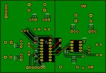
as the gerber files are lost and I wanted to build this project I made new boards. Iam very curious if this circuit really sounds better than a Naim DAC 🙂
Front view:
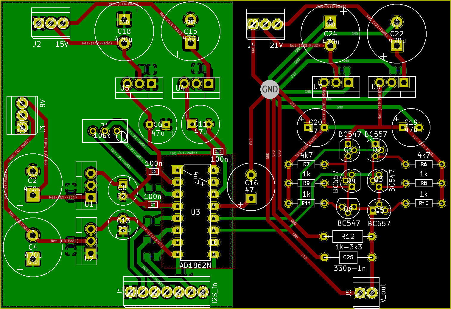
Back view:
I tried to star earth the analog section, and the digital section has a filled copper zone instead.
Any advice...?
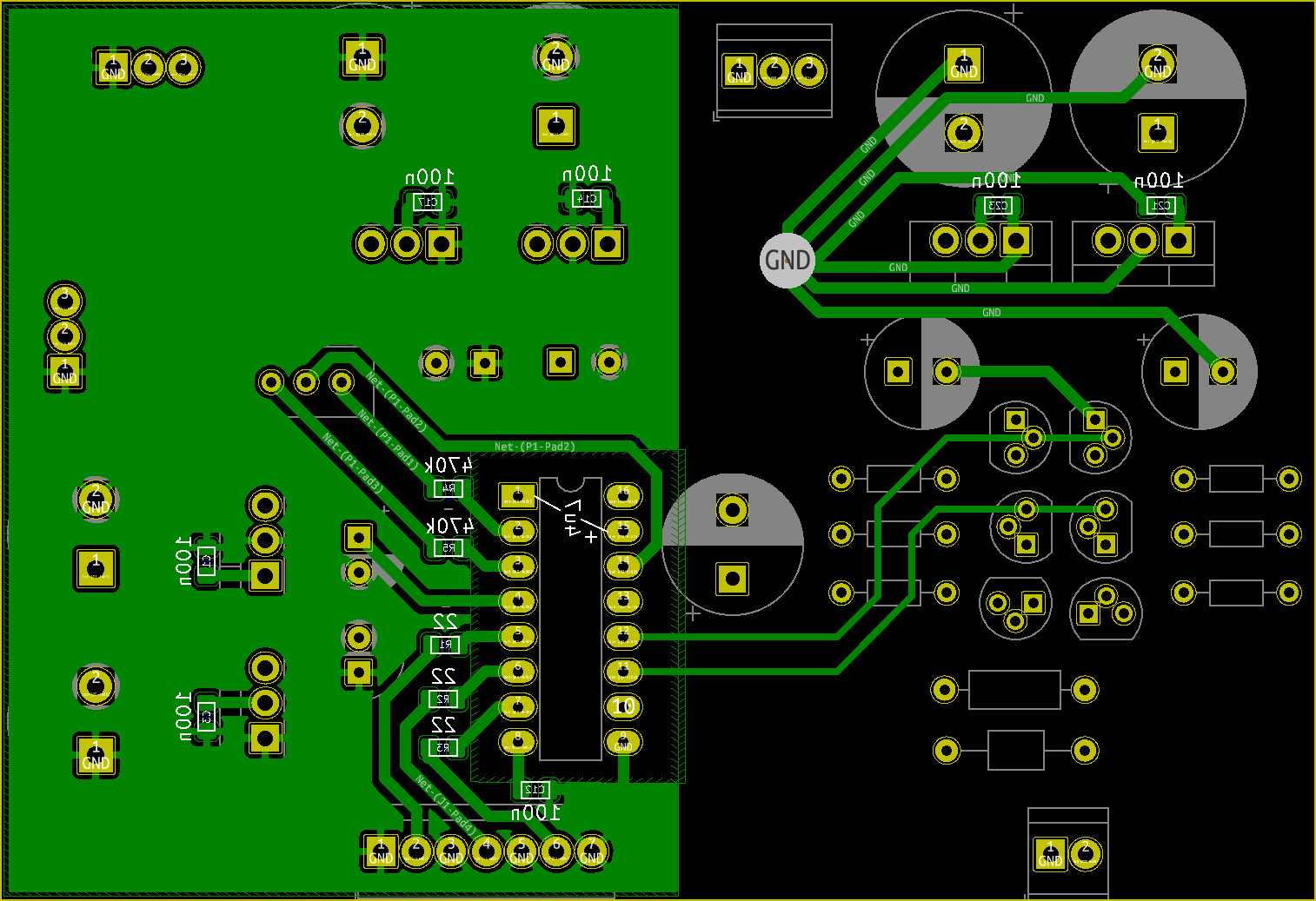
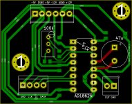
as the gerber files are lost and I wanted to build this project I made new boards. Iam very curious if this circuit really sounds better than a Naim DAC 🙂
Front view:
Back view:
I tried to star earth the analog section, and the digital section has a filled copper zone instead.
Any advice...?
Attachments
... Any advice...?
yes, if its I/V is from post #36
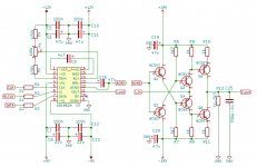
AD1862 PCB layout
then put something else in there, this I/V has not a nice sound at all, it's very flat, basic NE5532 opamp sounds more beautifully (I myself have compared it few years ago) ... there are much better solutions (better opamps
 , or @laserscrape tried audio transformers with a good result), build the PCB with Iout and try different I/V concepts to find the best for you
yes, if its I/V is from post #36
AD1862 PCB layout
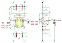
Yes, I tried to re-draw it:
this I/V has not a nice sound at all, it's very flat
But Painkiller wrote it sounds better than DACs by Chord and Naim...?
there are much better solutions (better opamps
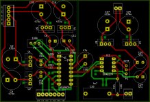
OK, I also re-draw your OPA627-based circuit:
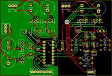
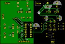
PCB front view:
PCB back view:
Questions:
- Painkillers schematic shows AGND connected to GND. I draw a separate star-GND for the analog section: where should I connect them together?
- For the OPA627: is it a good idea to have the 47p cap across the 1k4 resistor?
I will build both I/V versions and report about the sound. If successfull I will publish files (gerber, schematic, PCB). In any case big thanks to Painkiller and Miro for the inspiration!
Attachments
Last edited:
Did anyone else manage to put together a set of boards?
As your gerber files are lost I am trying to make a new PCB, but I am not sure about the routing as my skills are limited. Any help of you would be appreciated!
it sounds worse than NE5534 😀But Painkiller wrote it sounds better than DACs by Chord and Naim...?
You should connect them together under DAC chip.Questions:
- Painkillers schematic shows AGND connected to GND. I draw a separate star-GND for the analog section: where should I connect them together?
Best if you follow a solid GND plane, and don't cross the wires, like this: DAC AD1862: Almost THT, I2S input, NOS, R-2R
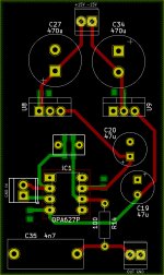
Yes, you can have it, ceramic C0G type only, or THT PP foil.- For the OPA627: is it a good idea to have the 47p cap across the 1k4 resistor?
Don't populate C35 (4n7), leave it empty, the AD1862 is audibly clean at the output.
it sounds worse than NE5534 😀
Just to make sure: you wouldn't prefer a NE5534 to a Chord/Naim, right...? 😀
Best if you follow a solid GND plane, and don't cross the wires
I saw you have some 0R bridges: I thought vias and solder points create problems such as jitter...? As for the analog section I could do without crossings like this (added a THT footprint to the 47p cap as you suggested):
Attachments
NE5534 is not for me 😀 I never heard Chord/Naim.
0R bridges is on power supply lines, not on signals. Most importantly, the NOS R-2R does not suffer from jitter problems, for the logical reason how it works. The biggest change in sound is in I/V section.
0R bridges is on power supply lines, not on signals. Most importantly, the NOS R-2R does not suffer from jitter problems, for the logical reason how it works. The biggest change in sound is in I/V section.
I never heard Chord/Naim
I seriously recommend: by all means have a decent Naim demo as soon as possible!!
don't cross the wires
OK, my PCB without crossings and flexible ground options (GNDs tied together at the power supplies outside the board or near the AD1862, selectably with solder jumpers):
Attachments
Drawing the GND wires in DACs into a star is not recomended, it's very bad, theoretically it could be but not like this.
It is recommended to do solid GND, and separate analog and digital only at critical points, not elsewhere (or not separate it at all) ... but don't trust me, follow the professionals if you want to learn something, because you obviously want to learn
Successful PCB Grounding with Mixed-Signa - Maxim Integrated
Last edited:
Drawing the GND wires in DACs into a star is not recomended, it's very bad, theoretically it could be but not like this.
It is recommended to do solid GND, and separate analog and digital only at critical points, not elsewhere (or not separate it at all) ... but don't trust me, follow the professionals if you want to learn something, because you obviously want to learn
Successful PCB Grounding with Mixed-Signa - Maxim Integrated
OK, thanks, I will study & learn 😎
if its I/V is from post #36 AD1862 PCB layout then put something else in there, this I/V has not a nice sound at all, it's very flat, basic NE5532 opamp sounds more beautifully
Just an update: I finally built and tested the circuits and found the discrete diamond IV stage (with original Philips BJTs) superior to the opamp stage (cleaner, more involving, more transparent, better PRaT). I compared it also to the DAC in my Naim integrated: the diamond IV won hands down. The opamp IV stage was also good, it has triple stacked AD844s followed by OPA627 (it did not sound very good with only one AD844: with 2 it was much better, with 3 it was fine, so I found the same as reported by others). I used multiple 3X7-regulated supplies and will upgrade them to super regulators in my final build (6 per channel plus the digital supplies from a separate transformer). BTW I tried PCM63s in place of the AD1862s and far prefered the latter. I also compared the glue logic NOS input to DF1704 and PMD100 on both DAC chips and IV stages: the PMD100 is clearly better than the very good DF1704, the glue logic was noticeably less refined but also not bad. So I ended with enough modules to make 2 DACs out of all this: DF1704->PCM63->opamp-IV and PMD100->AD1862->diamond-IV 🙂
 Moved to digital line level
- Home
- Source & Line
- Digital Line Level
- AD1862 PCB layout