Slightly disappointed. I opened this thread thinking - silent tube power supply..
16A PCB pins, internal switching, makes me think this isn't going to be your normal DIP8 package I take it?
Perhaps of interest to the solid-state Power-DAC headphone crew or digital clocking folks but nV is probably not going to make too much audible difference? (I know I'm opening a can of worms with at last question)
It’s a 4x4mm LQFN package. For some reason there’s a market for low noise LDO’s. So I don’t see why vastly improving efficiency, no heat with up to a 17v drop, and high current capability, would be a disadvantage. They can also be programmed to be inverting. Which isn’t a feature I’ve ever seen in a low noise LDO.
Show an application which uses both LOW noise and HIGH current. Maybe people will get excited.
Small size low noise high current laboratory power supplies anyone? So far a linear bench supply is a must have for any serious tinkerer.
B&K’s lowest noise bench supply has 100x the ripple noise of the silent switcher 3.
Model 9171B, Dual Range DC Power Supplies - B&K Precision
Model 9171B, Dual Range DC Power Supplies - B&K Precision
Amplifier, low noise power supply for a computer server/streamer. Or maybe you want to have a single 15-18v supply feeding a few of these with some set at 3-5v output without them burning to a crisp like what would happen with an LDO dropping 12-15v. It’s not essential to use all 16A of current capability to use this regulator.
Don't get me wrong I think that would be very nice.
4mm x 4mmm package size. I'm not sure I'd call that your average DIYer. I suspect the flow soldering with a microscope and a positioning system means it's going have to be on a Arduino-style breakout board (bang goes the nV). I'm assuming it will have to have heat vias on the bottom too. Only other way is to have PCBs prebuilt or at least partially.
I'm bad enough with screws on the floor now and I still have -0.25 vision! 😀
I thought more people would be excited about these around here. But maybe there’s nobody left who understands the significance of this IC.
I suppose there’s also the luddites who turn their nose up as soon as they hear “switcher”. Because regardless of the actual performance, every true audiophile knows that switching power supplies are horrible for audio.
Maybe for a minute think about the skill level of a DIY hobbyist, do they have the necessary knowledge and expertise to design multilayer pcb's to minimise radiated and conducted noise from a switching regulator. Do they have the understanding about the requirement for input filtering. Add to the mix unfriendly LQFN smd packages.
There’s several people on here that have the ability to populate these packages. I’m thinking Jan Didden could make a new version of his silent switcher:
Linear Audio Silent Switcher V3 – diyAudio Store
With 3 of these regs, less noise, 100x the current capability, and much less components on the board.
Linear Audio Silent Switcher V3 – diyAudio Store
With 3 of these regs, less noise, 100x the current capability, and much less components on the board.
Last edited:
And that board could be powered by a cheap, standard 18v laptop supply such as this:
Meanwell 18V Power Supply GST60A18-P1J
Just put a barrel connector input.
Meanwell 18V Power Supply GST60A18-P1J
Just put a barrel connector input.
These are hybrid regulators with linear output stages. By combining the technology in 1 package you get the efficiency of a switcher, and noise level of a very good LDO.
That's how I designed my silentswitcher 😎
But you always lose some efficiency in the linear regulator headroom. Probably half a volt or so.
A friend of mine is working on a silentswitcher with double the current output.
We'll let you guys know ;-)
Jan
Last edited:
It's not that hard soldering SMD components. I only have a regular magnifier lamp and solder iron, but I've hand soldered 2x3 mm 8-pin DFN package and similar. With the DFN package for instance, put some vias under the chip, use solder paste, stick the iron under the PCB and it will practically solder itself.

That's how I designed my silentswitcher 😎
But you always lose some efficiency in the linear regulator headroom. Probably half a volt or so.
A friend of mine is working on a silentswitcher with double the current output.
We'll let you guys know ;-)
Jan
I like being the dumbest person in the room.. it means you don't have to wait for people to catch up 😀 nice board already available 🙂
It's not that hard soldering SMD components. I only have a regular magnifier lamp and solder iron, but I've hand soldered 2x3 mm 8-pin DFN package and similar. With the DFN package for instance, put some vias under the chip, use solder paste, stick the iron under the PCB and it will practically solder itself.
The difficulty level is exponential when you have to deal with 24pin 4x4mm LQFN.
It's not that hard soldering SMD components. I only have a regular magnifier lamp and solder iron, but I've hand soldered 2x3 mm 8-pin DFN package and similar. With the DFN package for instance, put some vias under the chip, use solder paste, stick the iron under the PCB and it will practically solder itself.
View attachment 998328
Nice. I remember seeing a mini PCB heater bed and thinking that's a grand idea. I remember seeing some SMD soldering (paste with flux and drag soldered) but with the heat vias on the ground plane that seems possible with an iron and not have to have too much wattage.
The difficulty level is exponential when you have to deal with 24pin 4x4mm LQFN.
It’s super easy when someone else does it for you.
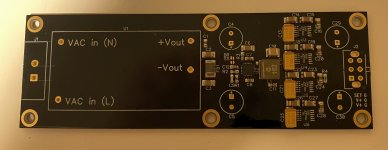
I made this killer little hybrid supply with a silent switcher 2 dropping the 12v input down to 5.5v, then into 4x LT3045’s in parallel set to 5v. 0.2uV ripple noise! 2A output.
Attachments
Last edited:
It’s super easy when someone else does it for you.
You complain about DIYers being not interested in switching regulators and now you're saying it needs to be commercially assembled in manufacturing quantities, in that case it's no longer DIY.
I find interesting that discussion (sort of) picked up only after addressing members of this forum as:
Not an approach I like. Positive attitude results in better response and suits well this forum.
maybe there’s nobody left who understands the significance of this IC
I suppose there’s also the luddites who turn their nose
many are only into DIY to save a few bucks. Not because they’re actually interested in the technology.
Not an approach I like. Positive attitude results in better response and suits well this forum.
You complain about DIYers being not interested in switching regulators and now you're saying it needs to be commercially assembled in manufacturing quantities, in that case it's no longer DIY.
If you don’t know how to do it yourself then your only choice is someone else doing it for you. This isn’t the case for many people on this forum though.
I find interesting that discussion (sort of) picked up only after addressing members of this forum as:
Not an approach I like. Positive attitude results in better response and suits well this forum.
All valid points.
The difficulty level is exponential when you have to deal with 24pin 4x4mm LQFN.
I'm looking forward to the challenge 🙂 Seriously, though, my eyesight seem to have began to age somewhat, so I might have to invest in a microscope for more convenient assembly.
Someone will have a board in the DIY shop with only the SMT parts populated. 9-18V single input from a barrel connector, and 3x 16a outputs that can be set from 1-17v.
- Home
- Amplifiers
- Power Supplies
- AD Silent Switcher 3. Game changing switchers!