Interesting.
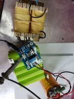
In your test setup, it looks like you're using a dual secondary in series.
For the sake of testing, what if you try using one secondary (or as is) and tightly twist the wires to your 4320 board with no snubber. Also tightly twist the wires to the 10uF.
Would it still ring?
There is no 10uF cap. The external cap is 10mF.
Tried half secondary. Lots more ringing, perhaps due to the half dcr. Cut down the input wires to almost nothing. No change.
Attachments
What values are in the snubber? I would try more aggressive snubbing as it is hard to overdo it. E.g. 470nF + 82R
Tried that. Went up to 2uF.
What type of rectifier is used in present-generation power amps currently shipping from Pass Labs?
What type of rectifier is in power amps currently shipping from Mark Levinson?
What type of rectifier is in power amps currently shipping from Luxman?
What type of rectifier is in power amps currently shipping from Dan D'Agostino?
What type of rectifier is in power amps currently shipping from Constellation?
What type of rectifier was used in (the ten most significant audio power amplifiers of all time)?
You are quoting mostly names that build Class A or AB amplifiers.
Once you are building class D, you need to be very careful, and if powering half bridge amplifiers synchro rectifiers can become very, very useful.
So the choice of your examples, for instance, is not representative. Also it contains mediocre amplifiers (Constellation) as well as outright crap (D'Agostino).
Roberto
The resistor does 100% of the work in a snubber. The series capacitor's only job is to provide a high impedance at 100 Hz / 120 Hz, in series with the resistor, limiting the resistor's power dissipation. I'd recommend choosing
(Capacitor impedance @ frequency "f" Hertz) >= 30 * (snubbing resistor in ohms)
where "f" is 100 or 120 Hz, depending on the local AC mains.
There's little or no benefit to choosing a bigger series capacitor, with an even lower impedance at "f" Hertz
(Capacitor impedance @ frequency "f" Hertz) >= 30 * (snubbing resistor in ohms)
where "f" is 100 or 120 Hz, depending on the local AC mains.
There's little or no benefit to choosing a bigger series capacitor, with an even lower impedance at "f" Hertz

There is no 10uF cap
Yeah, typo, ment 10mF.
🤔 Strange with this ringing you have.
Tried half secondary. Lots more ringing, perhaps due to the half dcr.
Could it be due to higher regulation of using one half.
I have a theory;
I don't know what trafo you have there, but it looks like a split bobin, but with primary and secondary on each side?
Could it be that your trafo has a very high regulation compared to, for example, a toroid?
So, when the 4320 turns on, the secondary drops enough to turn it off, then turn it on again, drop, turn off, turn on, drop (ringing).... until it stabilizes?
Exactly. R should be sufficiently low to allow quick discharge and C sufficiently high to form a high pass filter with fc 1/4 or less of the ringing freq.The resistor does 100% of the work in a snubber. The series capacitor's only job is to provide a high impedance at 100 Hz / 120 Hz, in series with the resistor, limiting the resistor's power dissipation. I'd recommend choosing
(Capacitor impedance @ frequency "f" Hertz) >= 30 * (snubbing resistor in ohms)
where "f" is 100 or 120 Hz, depending on the local AC mains.
There's little or no benefit to choosing a bigger series capacitor, with an even lower impedance at "f" Hertz
C = 4 / (2 * pi * R * f)
Where f is the frequency of observed ringing (that is 10kHz in the examples above). In some cases R should be as low as 10 - 20ohm. That would require higher C.
In general, there is no harm to pick lower than required R value unless it starts to dissipate too much or C becomes impractically large.
There's quite a few transformers listed in (this thread) whose Quasimodo-optimized snubber resistance is 10 ohms or less.
Could it be that your trafo has a very high regulation compared to, for example, a toroid?
So, when the 4320 turns on, the secondary drops enough to turn it off, then turn it on again, drop, turn off, turn on, drop (ringing).... until it stabilizes?
I don't think so. Without a snubber there is problem only at low currents, exactly where the transformer regulation is not important. There are no issues with the 4320 as long as you add a snubber and in many cases even without a snubber.
What happens if lower than recommended (optimized) R and proportionaly higher C is chosen so R*C remains? I suppose there is no other downside beside somewhat higher dissipation and need for bulker and more expensive C.There's quite a few transformers listed in (this thread) whose Quasimodo-optimized snubber resistance is 10 ohms or less.
For long I wanted to ask this question so I'm using this opportunity 🙂.
Gate drive looks perfect, that's good to know.The MOT adjustment is geared towards the frequency range this device is normally used at, max MOT is 3.6uS so it makes little if any difference at 50Hz. And the gate drive looks perfect. My layout is generally close to the app note but the mosfet is through hole. Not sure if this is critical, as i have no plans for 500kHz operation.
Looks like this has turned into a Quasimodo clone 🙂 High voltage, high dcr transformers are naturally immune but what i don't understand is the current dependence. Nothing much changes at the gate drive, yet the ringing disappears.
Problem with stuff that doesn't work like supposed to work is that the error can be:
By lack or misunderstanding of knowledge. I see lots of people chime innand you're testing those.
There is another and that is the assumptions we make
Assuming all parts are oke, but the sum of it isn't ;-)
I would also try a "normal" transformer, just to be sure the problem is not in plain sight and another is the assumption that 100Hz needs different layout than 500KHz.
They are the same, because the fet gets driven by a pulse that is made for both modes and only the slew rate is important, it sets the needs for the layout.
Having said that, I do think the problem is elsewhere, but it's good to know the rate of change sets the bar, not so much the frequency.
Good luck, you're on the right track!
Exactly.
I replaced FBR with Active Rectifier in my classA amp AN39 long time ago, because FBR was even with big heatsink running too hot. Now with AR it runs fine not even warm.
What myth?
Shirley, the issue is ... which makes the amp sound better - FBR or AR?
This is an example of poorly made video that may mislead many people. Poor documented and using wrong parts.One more myth put down:
Active rectification is used in industrial applications for over 70 years.
TEA2208T was discussed on this forum and I already mentioned, at least two times, this CAN NOT be used as a normal full bridge.
In fact, on 16 May I have wrote to channel owner here below mail.
"Hello Great Scott,
My name is Tiberiu Vicol and the owner of a small company in Romania specialised in synchronous rectifiers.
I follow your channel like many others. You have some great educational videos.
In your video
If fact the answer on your TEA2208 “problem" is on NXP site ->> https://community.nxp.com/t5/Power-Management/TEA2208-Switch-Speed-Waveform/m-p/1153083
Indeed this is targeted to SMPS input followed by PFC.
We make several high voltage, high current and high frequency full bridge rectifiers that are direct replacement for a diode bridge.
If you are interested to test and make a video about these, I may supply few to you.
Check us at https://evotronix.eu
Best regards,
eng. Tiberiu Vicol "
Still see no reason using it in audio...but anyway...everyone is entitled to its own opinion and the audio domain today is scarcely inhabited by reason....a few days ago I just found out in a store some 20 types of soft recovery diodes with heatsink mount working up to insane currents and voltages alsi quite efficient... also 150v /10 amps schotkys... there's tones of diodes for every possible application outhere snd I don't see the reason for supplying class A fancy audiophile units with a highly efficient bridge cause nothing in the audiophile world is about efficiency today.Class d amps get sold today for 1k ...40k $ which is pretty irrational cause the main reason for using efficient electronics was to get lower prices for anything associated to it...
With the current trends in audio we'll get back to 100watts/channel class A amps soon cause they cost the same as today's cherrished class D amps and I for one am not convinced of how better the best class D amps are over the old times class A amps...My ears at least don't hear the difference.
With the current trends in audio we'll get back to 100watts/channel class A amps soon cause they cost the same as today's cherrished class D amps and I for one am not convinced of how better the best class D amps are over the old times class A amps...My ears at least don't hear the difference.
Last edited:
Great Scott's video on the topic is failed. He doesn't know the area well and made a poor attempt.
Another youtuber, FesZ Electronics made a series of videos exploring the theory of active rectifiers, simulating and doing his own experiments and finally creating a DC supply for vacuum tube filaments. That's a great way of approaching the topic and finally implementing something in practice.
Another youtuber, FesZ Electronics made a series of videos exploring the theory of active rectifiers, simulating and doing his own experiments and finally creating a DC supply for vacuum tube filaments. That's a great way of approaching the topic and finally implementing something in practice.
Sadly, FesZ shows his misunderstanding of heater filament flash - portraying it as a bad thing that needs a solution.
He also then makes a raft of simulation modelling and circuitry decisions that imho aren't credible as they stand - from using a constant current sim part for the filament (rather than a resistance), and having a voltage source without any regard for leakage inductance or ESR, and wanting to insert a snubber, as well as a series inductor. And then not providing any bench prototype results.
He also then makes a raft of simulation modelling and circuitry decisions that imho aren't credible as they stand - from using a constant current sim part for the filament (rather than a resistance), and having a voltage source without any regard for leakage inductance or ESR, and wanting to insert a snubber, as well as a series inductor. And then not providing any bench prototype results.
I just watched version 2/2 of Fesz youtube.
Imho it was poor commentary to say that parasitic values were not added to a simulation due to simulation time - nowadays that is a myth. The lack of any attention to transformer winding resistance was just inexperience by Fesz, and that was easily seen by the 'flat-topping' of the transformer voltage waveform, and what is a major issue with respect to achievable dc voltage levels.
Another poor comment related to e-caps having 'high' series resistance, and the need to add parallel low value caps to manage that 'high' resistance. That is another myth.
And the main faux-pas was to include a series inductor, along with simulation effort to portray its usefulness, only to finally realise that he couldn't substantiate that design choice in the demo.
More poor comment was directed at the usefulness of wanting to achieve a dc current output rating that would cover say more than two 12AX7 (ie. 0.6A) and even to include output stage valves. And also to continue the myth that supressing heater turn-on current was going to provide a tangible service life improvement.
You should give him some feedback. I've watched some of his other videos and he certainly doesn't claim to be an expert, but seems to learn as he goes along.
It is rare to find people that are experts in their area and are willing to share it on youtube, making good videos in the process. Understandable, probably their $dayjob pays better. There are exceptions of course, but the youtube algorithm isn't favorable to them, so they are hard to find.
You have to turn into an entertainer with clickbaits etc. to survive on youtube. Good old electronic engineering isn't popular unless you make a show of it like naturals such as David Jones.
Have a look at the YouTube channel of W2AEW (link). He's an expert electrical engineer who is willing to share his knowledge. Including both the actual mathematics of the topic, and the physical intuition of what's going on + why. He doesn't falsely reassure viewers that electronics is no more complicated than whittling a stick or assembling a plastic model airplane.
- Home
- Amplifiers
- Power Supplies
- Active rectifier or full bridge?