Don't forget to check the scale on the graph. DC gain in your sim looks like just a little less than 6 dB. And it's only down ~0.2dB at 20K, and -3dB beyond 100kHz. I think you've pretty much got the right values there.
Ahh... Yep, I see you are right, or rather, I was right. That makes sense to me, but honestly I think I'd feel more comfortable if the roll-off started after 20KHz. Maybe I'll fool around with it a bit more. Good to know the results are what I expected.
I would increase the first to 0.5uS (~300kHz) and stagger them so that the feedback operates at least an octave above the passive filter (~600kHz). That opamp must be unity gain stable for that 100pF to operate.
Thanks. I'm going to have to think about this one because I'm not sure what it means to me yet. I may have follow-up questions 🙂 .
The 10K/100 pf form a 150 KHz. 6 dB shelving low pass filter. That helps cause the early roll off, but it should be flat again at ~300K. To get the step up to center (-3dB) at ~300K, just reduce R12 and R16 to 7.5K. 3.9K will get you -3 dB at ~600KHz. You could also reduce the 100pf to 50 or 27 pf with similar results.
To increase the frequency of the input filter to 318K simply reduce R11 to 50 ohms OR reduce C9 to 5 nf.
To increase the frequency of the input filter to 318K simply reduce R11 to 50 ohms OR reduce C9 to 5 nf.
BobEllis said:To increase the frequency of the input filter to 318K simply reduce R11 to 50 ohms OR reduce C9 to 5 nf.
You also have to think about the output resistor of the source feeding the filter 😉
\Jens
Right as always, Jens.
I got caught up in the ~0 impedance source assumption. I'd guess probably better to go a bit higher resistance and smaller cap to reduce the sensitivity to source impedance. Using 10K/100 pF would attenuate the signal 6 dB, which is compensated for with the buffer's gain.
I got caught up in the ~0 impedance source assumption. I'd guess probably better to go a bit higher resistance and smaller cap to reduce the sensitivity to source impedance. Using 10K/100 pF would attenuate the signal 6 dB, which is compensated for with the buffer's gain.
Ok, I've gotten myself a little confused. I've calculated out all my component values and everything seems to be well. One thing is still confusing me. I'm designing a 3-way crossover, but when I pass the HP signal from the woofer/mid board to the mid/tweeter board do I need to by-pass the buffer? If so, how do I do this?
Also, when I route the output of the HP and LP sections into the appropriate EQ and all-pass sections, this would seem as if it was done AFTER the buffer. Is this ok? Doesn't the buffer need to be the last step?
And ALSO! 😉 It doesn't seem as if all of the outputs and inputs on the board are clearly labeled as + and -. Whats the best way to determine the pinout for a given output or input?
Last one. Should I be using coax cable as the signal passes between sections and between boards or can I use regular stranded conductor wire with no negative consequences?
Thanks very much for your effort guys, I can't wait to get this thing playing.
I'd route the signals out from JP8 and JP15 to the mid/high board skipping the buffer. Similarly go from those pads to EQ and from EQ back to the appropriate JP to get to the buffer. Yes, the buffer should be the last thing in the chain.
Be sure to ground the unused buffer section (jumper the R21).
This is all single ended stuff, unless you opt for balanced in. Each input and output has a hot and ground connection. It shouldn't be hard to tell by looking at the board, but you can also use your ohmmeter to verify.
If you go with balanced inputs, they are labeled + and - the output will be single ended.
I use 26 gauge hookup wire with a hot and ground connection twisted lightly together. I read somewhere that using coax for signals inside an enclosure isn't a good idea. Could be bunk, but twisted pair works just fine, so why go to the trouble.
My mistake, in my last post when I said '-' I meant ground.
If I route the signal out of JP8 and JP15 to somewhere else (ie. EQ, another board, etc) where do I bring the ground connection from? To try to clairify, I'm bringing the signal from JP8 or 15, but there is a ground pin on the receiving end of that connection, what should I connect that to?
Also, if I want to bring the signal out of the HP or LP to go through EQ, all-pass, etc, but then bring it back for the buffer and gain adjust before it leaves the board to go to the amplifiers, where do I bring the connection back? It's leaving from the JP8 or JP15, but it would seem like I would want to bring it back to the same place?
Hope that makes sense.
m0tion said:My mistake, in my last post when I said '-' I meant ground.
If I route the signal out of JP8 and JP15 to somewhere else (ie. EQ, another board, etc) where do I bring the ground connection from? To try to clairify, I'm bringing the signal from JP8 or 15, but there is a ground pin on the receiving end of that connection, what should I connect that to?
I just bring the ground wire from the board with a handy ground connection and apply a little heat shrink at the JP8/15 end to keep the ground wire attached. I think this helps avoid ground loops, but I may be mistaken.
Also, if I want to bring the signal out of the HP or LP to go through EQ, all-pass, etc, but then bring it back for the buffer and gain adjust before it leaves the board to go to the amplifiers, where do I bring the connection back? It's leaving from the JP8 or JP15, but it would seem like I would want to bring it back to the same place?
Hope that makes sense.
Bring it back to pin 2 of the JP, which connects to the buffer inputs.
Bring it back to pin 2 of the JP, which connects to the buffer inputs.
Hah, of course. I actually feel silly for having asked this now.
I just bring the ground wire from the board with a handy ground connection and apply a little heat shrink at the JP8/15 end to keep the ground wire attached. I think this helps avoid ground loops, but I may be mistaken.
I'm sorry. I don't understand your meaning. Let me rephrase my question in case that was the problem.
When I connect pin 1 of either JP8 or JP15 to pin 2 of an EQ or all-pass section, what should I connect pin 1 of that EQ or all-pass section to?
I think you probably understood my question the first time, but for some reason I can't understand your answer.
Thanks again, very much, for all your help.
You usually don't need to connect it at all, especially for using EQ, etc. on the same board - the ground plane provides the ground connection for the sections.
If using an EQ on another board (say you need three notches in the midrange section), I solder a piece of hookup wire to pin 1 of the EQ section and twist that around the signal wire. This wire doesn't actually connect to anything. A piece of heat shrink at each end holds it together. I think it might make a bit of a shield, which is probably totally unnecessary, but I like the way it looks. 😉
Multiple boards will all be connected via their PSU grounds. Since there isn't a separate signal ground this should be sufficient, and any other ground connection risks ground loops.
When using a different board for EQ etc. you can use a wire as Bob said to provide some shielding or u can use shielded wire.In both cases you should connect the shielding at one side of the wire to ground only.As long as you don't connect the shielding on both sides you are never going to create a ground loop.
Kees.
Kees.
Bob:
Thanks. One more if you don't mind =). I've heard you mention on a number of occasions that you like active crossovers because if you want to change something all you have to do is swap a couple of cents worth of resistors and capacitors. I'm wondering how you do this? Maybe it's just me, but I find desoldering on a PCB to be very tricky and I've ruined a few solder pads in my day. Any tips? Any way that you know of to "temporarily" solder a joint for components you aren't sure about?
Thanks. One more if you don't mind =). I've heard you mention on a number of occasions that you like active crossovers because if you want to change something all you have to do is swap a couple of cents worth of resistors and capacitors. I'm wondering how you do this? Maybe it's just me, but I find desoldering on a PCB to be very tricky and I've ruined a few solder pads in my day. Any tips? Any way that you know of to "temporarily" solder a joint for components you aren't sure about?
Hi,
Our PCB designer, Jens, posted a pic showing a couple of pins/sockets for mounting 5mm pitch capacitors. Simply unplug and swap in new caps.
You could easily insert solder pins for all the frequency setting resistors. Then just tack solder resistor to the pins. It becomes very easy to unsolder and re-attach without damaging your PCB/pads.
Even better would have been to use dual in-line sockets/headers for all the frequency setting resistors and caps. Then just swap out dil headers with alternative components already set up in each header.
Jens' sockets are a great idea to avoid desoldering.
Yep, desoldering can be a real pain. With a lot of trial and error (and damaged boards) I have found that using a big tip on the iron (2 mm) and setting it around 425 C works pretty well. It's hot enough with enough thermal mass that it stays hot enough to melt the solder before the trace to board joint gets loose.
I usually clip the leads of resistors and just grab the remainder with needle nose pliers to pull it out when I heat it. If I have to change a cap I push it towards the lead I am not heating so that it moves as soon as the solder melts. Sometimes it takes a little back and forth rocking, heating one lead and then the other to get the cap out.
The idea is get the lead out of the hole as quickly as possible. Then assuming that you didn't overload the joint you just need to use your solder sucker to open up the hole. It helps to have a vice to hold the board.
If there is a large amount of solder, you may need to use solder wick. Of course the copper mesh is a great heat sink, so it's important to have a big, hot tip so you can get the solder cleaned up quickly. I haven't had much luck with an iron <40W and wick.
Hope that helps. Practice on a dead board.
Wow, yeah sockets seem great. I'm having trouble locating the part on digikey though. Does anyone know the formal name for the type of sockets I would need?
Hi
Try looking at this link: http://portal.fciconnect.com/Comergent/en/US/fci/drawing/58805.pdf
Sometimes I simply use standard DIL IC sockets that I cut in pieces with my side cutting pliers. The remove the plastic and you are ready to go.
A word of caution: Any loose components in a filter connected to an amp and speakers might make life interesting !
\Jens
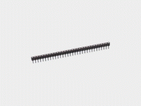
The connectors are called SIP breakaway strips.I couldn't find them on Digikey but Mouser carries them.
http://www.mouser.com/catalog/630/1179.pdf
type F is the one i used.
When a connection would fail it could make some interresting noise i agree. As long as you don't have a fully DC coupled system your speakers and Amp should be ok though.
You can always solder the parts in the sockets whem you are satisfied with the final result.
Kees.
- Status
- Not open for further replies.
- Home
- Group Buys
- Active filter board GB