You'll need to run the buy if you want them in 2007 - I'm pretty much out of spare time for a while. I might be able to put some of my own projects together but won't be able to run a GB. Sorry.
OK, I'm ready to start building soon 🙂
I do have a few noob questions though before I buy all the wrong stuff. 😉
Are these the right filter caps to use?
http://uk.farnell.com/jsp/endecaSearch/partDetail.jsp?SKU=1005977&N=0
Or can I use these?
http://uk.farnell.com/jsp/endecaSearch/partDetail.jsp?sku=106780
Someone at work said because they would have to stand upright on the board, the length of the wire would be too long because it would be slightly inductive and cause problems plus they are for low frequency applications.
Is this the correct type of LM6172 to use?
http://uk.farnell.com/jsp/endecaSearch/partDetail.jsp?SKU=4772544&N=0
I would like to use sockets but can't find any on the Farnell site because I have no idea what they are called 😀 Any clues please plus what would be the correct type of LM6172 to use with sockets?
Are these OK for the board level bypass caps?
http://uk.farnell.com/jsp/endecaSearch/partDetail.jsp?SKU=1198322&N=0
I've been advised they burn easily though if not soldered carefully 😀
As there don't seem to be 5nf caps available, is it OK to use a 4.7nf and 0.3nf together - one on each side of the board?
I think I (probably) have everything else covered 🙂
Sorry - that's quite a few questions but any help appreciated 🙂
Oh, also - because I don't have DC blocking caps in my amps, should I add them to the the filter boards?
Hi,
the axial Vishay do not fit the PCB.
This is audio, the caps are ideal for this low frequency use.
where is the 4.7nF? does it need 1% accuracy? does it need better than 10% accuracy?
When you come to gain setting and frequency setting then select resistors to better than 0.3% and if you can achieve it, capacitors to better than 1%.
If you arrange for values to be equal you can match, even though the absolute value is incorrect (due to lack of availability or poor instrumentation).
Thanks for your reply
The 4.7nf (well, 5nf according to the spreadsheet) are C15 and C17 in low pass filters and band pass filters, I don't know what accuracy they need, the manual just says get the tightest tolerance I can find / afford.
Schematic http://www.delta-audio.com/Filter_DIYAUDIO/Active_filter_DIYaudio.com.sch.pdf
I guess I should really adjust the spreadsheet values to fit the available component values.
The resistors I'm going to use are std 1% metal film. I couldn't find any suitable caps which are better than 5%.
Thanks for the advice 🙂
Hi,
C14 through C17 are frequency setting caps. Similarly C3 through C6.
These are those that I said to match better than 1%.
Buy lots (many) of 5% tolerance and select into groups of four that are closest.
C14 through C17 are frequency setting caps. Similarly C3 through C6.
These are those that I said to match better than 1%.
Buy lots (many) of 5% tolerance and select into groups of four that are closest.
I know it is possible to write a spreadsheet that chooses only standard values, but I don't know how. I figured by the time I learned how I could go through several iterations and find values that worked well together. If an Excel whiz wants to whip up a version like that, I'd be happy to host it. 😉
AndrewT said:Hi,
C14 through C17 are frequency setting caps. Similarly C3 through C6.
These are those that I said to match better than 1%.
Buy lots (many) of 5% tolerance and select into groups of four that are closest.
OK, understood.
I have a DMM which measures capacitance that I recently bought from Ebay - I knew it would be useful 😉
Thank you 🙂
--
It's easy enough for me to adjust my values to get std values for the components 🙂
Hi,
the freq setting caps and resistors in both the high and low pass side of each frequency need to match. If you can, try also to get match between left and right, but L/R matching is much less important when you are already aiming for <1 or 2%.
You NEED 4Rs and 4Cs that closely match for each frequency that uses a 2pole turn-over. If you go for 4pole you need double the number. You can use 8Rs and 8Cs if you want to try matching Left and Right.
Keep in mind that absolute accuracy is not a problem. It does not matter that the frequency is 1360Hz rather than 1300Hz.
All this matching is much easier if the Rs and Cs are equal rather than ratios of each other.
BobEllis said:Yes, all shipped, but yours may take a few days longer as it had to go airmail. Argentina does not accept USPS Global Priority Mail.
Already shipped my order? Have you the shipping date?
Regards
Jose
Jose,
Yours went out with the rest of the group on 12/16 USPS Airmail Letter post. This service is advertised as 4-7 working days, although that does not seem to factor in clearing customs.
Bob
Yours went out with the rest of the group on 12/16 USPS Airmail Letter post. This service is advertised as 4-7 working days, although that does not seem to factor in clearing customs.
Bob
Ok, understood about the PS groupbuy. Let me ask this. I looked at the PS schematic and it seems pretty complex. What are the advantages of this type of PS arrangement over just a simple Toroid -> BR -> Filter Caps -> Fuses? Is there a simpler way to make a PS to power these boards or do I really need to follow the PS schematic on your website to get good results?
This circuit provides a much quieter supply than just using capacitive filters. Using an LM7815 and LM7915 would be better than nothing, and fairly simple to build on prototype board.
Bob:
Let me ask it this way. If you're in my shoes and you want to build these circuits, but don't have the PS boards, what do you do?
Let me ask it this way. If you're in my shoes and you want to build these circuits, but don't have the PS boards, what do you do?
Hi,
in the absence of PSU PCBs use lm317s with a cap on the adjust pin.
transformer Vac = regulated Vdc. (except at very low DC voltages then add 1or 2Vac i.e. 15Vac for 15Vdc, 10Vac for 9Vdc, 7Vac for 5Vdc).
in the absence of PSU PCBs use lm317s with a cap on the adjust pin.
transformer Vac = regulated Vdc. (except at very low DC voltages then add 1or 2Vac i.e. 15Vac for 15Vdc, 10Vac for 9Vdc, 7Vac for 5Vdc).
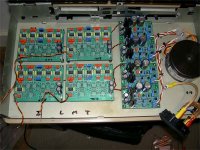
OK, almost everything is done apart from connecting the RCA sockets because I'm waiting for the ally sheet to land so I can make the back panel.
I've tested the PSUs and I'm happy with them - 15.08v to 15.11v 🙂 No magic smoke escaped either 😀
I've just checked the DC offset at all the output pads and it's between 11mv and 26mv with nothing connected (and everything still floating about in the case 😉)... Is this OK / safe / about what I should expect?
I've enjoyed putting this together. I can't wait to hear it... 😀 Thanks for creating the group buy 🙂
Attachments
Hello again and sorry for what must seem like daft questions to you experienced people.
I've tested 3 boards and found the same issue with all of them.
I'm assuming I've connected them up wrong because I've checked every component placement and value and every solder pad with a jewellers eyeglass and not found any mistakes. I'm OK at soldering so doubt I've heat damaged anything either.
With the filter board connected between the preamp and amp but switched off, I get a really - and I mean really loud 50hz tone - it isn't like mains hum - it's a clean sine wave sounding noise. With the unit on, it disappears to leave very quiet electrical noise - barely audible.
I get what sound like the correct frequencies from the outputs but they start at normal volume and get quieter over the next 10 seconds until the level is at about 10% of the initial level. If I turn up the preamp, the sound gets quite distorted but it's still pretty quiet. It's almost like the unit is running out of power.
I've attached a pic of a board with the connections I've made drawn on so I was hoping someone would be able to tell me what I've done wrong please? I'm using single ended inputs.
Is anything supposed to be grounded?
Attachments

Hi,
the four extra pads by the V+ & V- are 0volt/common.
They are kept separate for those that run separate positive regulators and/or dual rectifiers from dual secondaries.
If you use a single 0volt reference then only one 0v pad needs a connection.
I suspect the decoupling are charging up asymetrically and pulling the 0v to one rail giving the delay and distortion you are hearing.
This may also be the reason for power off hum. No 0v reference.
But, post 596 shows a twisted pair from each regulated PSU.
Thanks again for your help 🙂
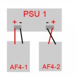
Yes, I've connected a pair from each board to each PSU. See attached diagram.
How should I wire the PSUs to the board? Connect each -ve from all PSUs to a common point and then connect each -ve from all boards to the same point?
Sorry for not understanding this properly.
If poss, may I have a diagram to show me how the power should be connected?
Attachments
- Status
- Not open for further replies.
- Home
- Group Buys
- Active filter board GB