So from a pragmatic, functional point of view, it also seems fair to think of IIR filters as a subset of FIR.
But this is absolutely not correct. As I stated in my post, you could imagine an IIR filter as the combination of an FIR filter and an all-pole filter, but this is the exact opposite of what you state - and even then only useful for certain optimisation procedures. Better to think of them as two different tools and pick the best one for the particular job at hand: A final crossover/equaliser will therefore likely incorporate examples of each.
But this is absolutely not correct. As I stated in my post, you could imagine an IIR filter as the combination of an FIR filter and an all-pole filter, but this is the exact opposite of what you state - and even then only useful for certain optimisation procedures. Better to think of them as two different tools and pick the best one for the particular job at hand: A final crossover/equaliser will therefore likely incorporate examples of each.
Honestly, I can't find reason to bother imagining IIR that way, despite any technical correctness. Thinking in broader terms makes more sense to me.
Sure, of course they are different tools.
And a giant Yes, I completely agree with "A final crossover/equaliser will therefore likely incorporate examples of each"
'Examples of each', which I routinely put into one FIR file.
Such as min phase driver EQ's, lin phase xovers, and max phase driver adjustments.
Maybe I'm making a mistake automatically associating IIR with minimum phase (pls ignore all-pass for now). Or maybe that's just the missing piece in this conversation..
But i do make that association, and it's implicit in the way I see IIR capability as a subset of FIR capability.
Pls advise if you think this IIR = min phase association is incorrect...
Excelent topic, and at the right time.
I'm building a 3 way composed by (theoretical XO points):
- Beyma 15p80nd => 50-300Hz
- AE TD12M => 300-1600Hz
- Beyma TPL 150H => 1600-20Khz
DSP will be a Monacor DSM-48LAN.
I will be following the approach documented here:Grimm Audio’s LS1 Speaker design
I have a calibrated Umik-1, and available space to take free air measures to select proper XO points.
My main question ATM, with the tools i have, how can i measure the delay time between drivers, to perform a proper time alignment through DSP?
OK, thank you. You may have clarified what I was looking for.
Based on your post, EQ can be applied to each individual channel, for example one for the tweeter, and one for the woofer. And of course, there is also one FIR filter for the tweeter and one FIR for the woofer.
Your post also implies that EQ can be applied to the front end signal before going into each individual filter for the tweeter/woofer.
Yes, good diagram. The front end EQ is a good way to handle source material vagaries imo.
The big thing is to put the EQ's that tune the individual drivers into their own respective FIR filters, not into the following driver channel PEQs.
You can do that, but my vote is to only do that to make adjustments to what didn't take correctly with the FIR file. And if the PEQs do correct the FIR response, I just go add them into the FIR file for less complication...
My main question ATM, with the tools i have, how can i measure the delay time between drivers, to perform a proper time alignment through DSP?
looking it from phase curve
you need to know how type of crossovers work what you wanna use (wraps phase a lot, a little or little to non)
when phase curve and frequency response matches you´re good to go.
i some times use rew but harder cases like in-car i use dual channel fft

Found old file from my el cheapo ob, can you guess crossover points from this? 🙂
when phase curve and frequency response matches you´re good to go.
i some times use rew but harder cases like in-car i use dual channel fft
Found old file from my el cheapo ob, can you guess crossover points from this? 🙂
Last edited:
As i mentioned above, i'm considering following the same approach documented on the LS1 Speaker design, so the plan is to use LR 4th order filters.
Is there any documentation that could explain how to use phase measurements to select the delay between drivers?
Is there any documentation that could explain how to use phase measurements to select the delay between drivers?
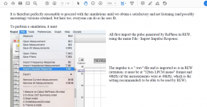
OK, so I found the answer to one of the question I asked before. That is, once you find the FIR from RePhase, how do you measure the affects of RePhase.
Apparently, in REW, you can import the impulse response from RePhase and I guess REW will convolve RePhase impulse response with the measurement.
Apparently, in REW, you can import the impulse response from RePhase and I guess REW will convolve RePhase impulse response with the measurement.
Attachments
Honestly, I can't find reason to bother imagining IIR that way, despite any technical correctness. Thinking in broader terms makes more sense to me.
Sure, of course they are different tools.
And a giant Yes, I completely agree with "A final crossover/equaliser will therefore likely incorporate examples of each"
'Examples of each', which I routinely put into one FIR file.
Such as min phase driver EQ's, lin phase xovers, and max phase driver adjustments.
Maybe I'm making a mistake automatically associating IIR with minimum phase (pls ignore all-pass for now). Or maybe that's just the missing piece in this conversation..
But i do make that association, and it's implicit in the way I see IIR capability as a subset of FIR capability.
Pls advise if you think this IIR = min phase association is incorrect...
The reason in the broadest possible terms is that FIR filters are inherently finite in their extent and therefore, in most applications, an FIR filter is an approximation to a target response. By contrast an IIR filter can be exact (subject to sufficient processing accuracy), for example, if we desire to use an analogue filter as a target response in a crossover design.
Your particular choice of FIR filter, for example, might be more efficiently implemented using IIR blocks for the crossover components and even elements of the EQ, which would leave the phase alignment to a separate FIR filter or realised in the IIR filter zeros - but that distinction is in the end pedantry.
As to the the assertion that IIR filters are always minimum phase, that is not correct. If there are no zeros in the filter - that is, if the FIR part is not used, then the remaining all-pole IIR filter will be minimum phase. But the ability to add zeros in an IIR filter allows non-minimum phase responses too. (Remember also that a non-minimum phase response can be constructed from cascading a minimum phase filter and an all-pass filter, but I will ignore that at your request...)
But a minimum phase response is different from a linear phase response which is necessarily two-sided in time (acausal) and hence precludes the use of recursive IIR filters where the feedback necessitates its causal, one-sided response. A linear phase FIR filter will still be an approximation, however, since it is impossible to find a delay sufficiently long to encompass all of negative time.
With an abundance of digital processing power, there might appear to be little to encourage people to bother to understand matters more fully. But FIR filters are not a subset of IIR filters, and each has their different design compromises that are well worth taking the time to understand if maximum fidelity is the target.
Imagine if a doctor refused to learn to speak Latin..Honestly, I can't find reason to bother imagining IIR that way, despite any technical correctness.
Others may not be detecting when your claims are based on a limited subset of situations, or when your conclusions are solid or just assumptions.
I think the point that mark is trying to make is that an FIR filter can in practical terms be made to have the same response as an IIR filter in that it can be made causal.
Using the word 'subset' is not right when describing the workings of the filters which soundbloke has done a very good job of explaining.
Pos the author of rephase posted this fairly recently which seems relevant to the discussion
Using the word 'subset' is not right when describing the workings of the filters which soundbloke has done a very good job of explaining.
Pos the author of rephase posted this fairly recently which seems relevant to the discussion
I think the IIR vs FIR is not only a matter of phase or delay, but more a matter of (CPU/DSP) power and limitations.
As a matter of fact FIR can do *everything* IIR can, including zero delay minimum-phase corrections (with time domain convolution at least), with zero drawback (beside power, but this is relative when you see the power consumption of an openDRC for example).
Yes, you can do FIR correction with zero delay (that is what I am currently running on my speakers).
And of course FIR can also do things IIR cannot do like linear-phase corrections, or very complex (or steep) corrections that would imply a great number of biquads (which brings complications I will cover in the next paragraph), or even purely temporal corrections (reflection cancellation, reverb, etc.).
And this brings another point where FIR is at an advantage compared to IIR: quantization errors.
IIR biquad implementations do generate errors because of the recursive nature of the filter scheme.
Even high precision implementations will generate quantification noises if the Q is high enough and/or the frequency low enough (ie long ringing, implying more accumulated errors). The level of this noise depends on the precision of the calculations, but the more filters you add the more noise you get, and this kind of noise is not as easily masked as harmonic distortion and the like (eg a single LF tone can generate a fullband noise).
In contrast FIR convolution is a direct calculation (even in its frequency domain form), does not depend on the correction itself, and not prone to errors. Errors will also not accumulate when adding multiple filter points. You can use thousands of EQ points in a FIR correction without increasing errors.
One last advantage of FIR vs IIR is correction portability: when importing a correction from one IIR crossover unit (or software) to another you never really know what you will get: filter conventions might vary (constant Q vs proportional Q, fc position for shelving, etc.), as well as their technical implementation (frequency response differences depending on sampling frequency in the UHF, as well as many strange behaviors).
FIR on the other hand is very predictable: once you have designed a correction (using rephase or another FIR tool) you can implement it in any convolution engine and get a predictable result based on the number of taps at hand.
This is an often overlooked point, but major nonetheless as many people are using corrections made for a given processor in another, and get frequency response variations that they often associate with audio qualities or defects of a unit, whereas it is "only" a difference in transfert function.
In short, if you have the processing power FIR only has advantages compared to IIR 🙂
OK, so I found the answer to one of the question I asked before. That is, once you find the FIR from RePhase, how do you measure the affects of RePhase.
Apparently, in REW, you can import the impulse response from RePhase and I guess REW will convolve RePhase impulse response with the measurement.
You are not measuring the effects of rephase by doing that, but it is possible to simulate the effects of the convolution by applying it to a measurement in REW.
An easy way to think of convolution is multiplication (time domain). To convolve two measurements together you multiply them.
REW can do this in trace arithmetic with the A*B function. The SPL will increase so it will need to be lowered afterwards probably around 80dB more or less depending on the levels of the files combined.
If your original measurement was good the simulation will be very close to reality. This is where it can be beneficial to simulate the response of the filters rather than measure them. It will be immediately obvious if you stuffed something up and won't result in letting out the magic smoke 😉
So do you mean REW will convolve the RePhase FIR with the measurement as a post processing step (after measurement)? That is it would not be done in real-time?
Also, along with the discussion of FIR vs. IIR, are the PEQ's in miniDSP implemented using only IIR (NOT FIR)?
Yes it is a manual operation that can be performed on a static measurement.
Convolving the filter with the measurement in REW will give a very accurate prediction of the result. To measure the effect the filter would have to be loaded into a realtime convolution engine in software or hardware.
Convolving the filter with the measurement in REW will give a very accurate prediction of the result. To measure the effect the filter would have to be loaded into a realtime convolution engine in software or hardware.
Rew and Umik for measuring, Balanced MiniDsp for voicing and crossover.
The system I am building; Crown CTS amps with USP3 input cards, they have 16 some odd bands of minimum phase peq, crossover, delay, and limiter/compressor.
Looking at the Crown Itech for linear phase crossover, but a nice sound card in ran with Acourate might be the better choice, which ever gives the lowest latency.
"If a crossover is well designed and has good phase tracking through the crossover region and there is no magnitude issue caused by it, in most cases it will be very difficult to hear the difference between that and the same crossover made phase linear" - I forget....Fluid did you say this?
Last edited:
Yes. The IIR and FIR abilities of the MiniDSP are totally separate and can be used at the same time. The FIR abilities of most MiniDSP hardware is very tap limited. I have been able to make some filters for the MiniDSP that are a fairly good match to high tap count filters by using the FIR above 500Hz and saving the IIR PEQ's for the lower frequencies. Rephase can generate the .bin files needed for the minidsp, The file format is IEEE754 raw 32bit float pcm with the .bin extension they can be generated by other software too and the extension changed manually.Also, along with the discussion of FIR vs. IIR, are the PEQ's in miniDSP implemented using only IIR?
Most FIR filters use a centred impulse which means there is latency. Some VST plugins allow the EQ parameters to be changed in realtime but there is usually a delayed glitch while the processor regenerates the filter.
Yes. The IIR and FIR abilities of the MiniDSP are totally separate and can be used at the same time. The FIR abilities of most MiniDSP hardware is very tap limited. I have been able to make some filters for the MiniDSP that are a fairly good match to high tap count filters by using the FIR above 500Hz and saving the IIR PEQ's for the lower frequencies. Rephase can generate the .bin files needed for the minidsp, The file format is IEEE754 raw 32bit float pcm with the .bin extension they can be generated by other software too and the extension changed manually.
Most FIR filters use a centred impulse which means there is latency. Some VST plugins allow the EQ parameters to be changed in realtime but there is usually a delayed glitch while the processor regenerates the filter.
Thank you for your response.
Based on the link from miniDSP below, it seems like one could purchase a OpenDRC-D unit and download the FIR impulse from RePhase into the hardware. Therefore everything will be done in realtime, and also one can measure the affect of RePhase directly without having to do any post-processing as a simulation.
If one decides to do RePhase in software, one option would be using JRiver and have JRIVER convolve the RePhase FIR before it sends the music stream to the DAC.
If you're using Window Media, I think you may have to use a third party convolver software (such as Equalizer APO) in order to work with Window Media.
rePhase FIR Tool
Last edited:
Yes you can upload a rephase generated bin file into any of the FIR capable MiniDSP units.
Your version of realtime and mine must be quite different. It will take probably five minutes to save a file from rephase load it into the minidsp and be ready to take a measurement. If you want to tweak something, another five minutes plus whatever time it took you in rephase to make the correction.
It will take no longer to convolve the rephase filter in REW with a base measurement, probably less once you get used to it. To make a filter that REW can import directly choose 32 bit IEEE wav. Import impulse, A*B, level reduce, see what you got.
I use Jriver in my system to convolve my DRC filters. This in no way could be considered a real time process. I use REW as a virtual check with A*B to see if I got what I was aiming for. Often I haven't so I start again. Measuring in real life is a total PITA for most people with families and restricted volumes. Virtual testing can be quite helpful.
Last edited:
- Home
- Loudspeakers
- Multi-Way
- Active DSP: Please post your software and equipment