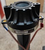
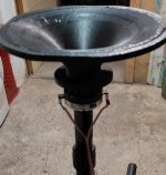
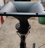
r0 = 9.5 for DE250?


There is a difefrence between GridExport:f360 and STL - no adapter.
There is a difefrence between GridExport:f360 and STL - no adapter.
Last edited:
Could you please show the profile for this one. I tried to enter them into R-OSSE calc. but was unsure... arcterm?The design goals were (pretty standard):
- consistent DI (throat adapter to prevent beaming)
- wide coverage
- directivity control at least down to ~1000hz
Here's the ATH script for this version:
Code:; ATH 4.9 20230530 ; MoniHorn v2 ; ------------------------------------------------------- ; CircSym mode ; Throat adapter Throat.Ext.Angle = 5 Throat.Ext.Length = 22.5 R-OSSE = { R = 197.15 a = 39 r0 = 9.5 a0 = 23 m = 0.76 r = 0.30 q = 3.65 k = 18.6 b = 0.0 arcterm = 160 } Rot = 0 .....
//
Also, I should say I don't use GridExport:f360. I don't know what that produces. However, the configuration file generates a shape inside the DE250 that looks like the above.
CinnamonRolls you have it right. Jzagaja you are missing the 23 degrees rotation.
We indeed used that shape inside the DE250. The sharp transition we smoothed with a continuous curve (G3) of radius of 50mm.
Because the CAD was made in Solidworks I used the following equations within SolidWorks’ equation driven curve(maybe someone else also is lucky and has access to SW and wants to use ATH in it):
for Xt :
((1/(2*(tan("a"pi/180)^2)))(sqr((2*"k""r0"*tan("a0"*pi/180))^2-4(tan("a"pi/180)^2)((("k""r0")^2)-("Radius"+"r0"("k"-1))^2))-(2*"k""r0"*tan("a0"*pi/180))))(sqr("r"^2+"m"^2)-sqr("r"^2+(t-"m")^2))-"b"((1/(2(tan("a"pi/180)^2)))(sqr((2*"k""r0"*tan("a0"*pi/180))^2-4(tan("a"pi/180)^2)((("k""r0")^2)-("Radius"+"r0"("k"-1))^2))-(2*"k""r0"*tan("a0"*pi/180))))(sqr("r"^2+"m"^2)-sqr("r"^2+(1-"m")^2))*t^2
for Yt:
(1- t^"q")(sqr((("k""r0")^2)+(2*"k""r0"*tan("a0"*pi/180))((1/(2*(tan("a"pi/180)^2)))(sqr((2*"k""r0"*tan("a0"*pi/180))^2-4(tan("a"pi/180)^2)((("k""r0")^2)-("Radius"+"r0"("k"-1))^2))-(2*"k""r0"*tan("a0"*pi/180))))*t+(tan("a"*pi/180)^2)((1/(2*(tan("a"pi/180)^2)))(sqr((2*"k""r0"*tan("a0"*pi/180))^2-4(tan("a"pi/180)^2)((("k""r0")^2)-("Radius"+"r0"("k"-1))^2))-(2*"k""r0"*tan("a0"*pi/180))))^2*t^2)-"r0"("k"-1))+t^"q"("Radius"+((1/(2(tan("a"pi/180)^2)))(sqr((2*"k""r0"*tan("a0"*pi/180))^2-4(tan("a"pi/180)^2)((("k""r0")^2)-("Radius"+"r0"("k"-1))^2))-(2*"k""r0"*tan("a0"*pi/180))))(1-sqr(1+(tan("a"pi/180)^2)(t-1)^2)))
t1=0.0
t2=1.1
Within this equation we used:
k = 18.6
a0 = 23
r0 = 9.5
a = 39
q = 3.65
r = 0.3
m = 0.76
b = 0
Radius = 223.9
Somehow this radius resulted in a 440mm horn so we used it. Note the plug and smoothing of it doesn’t come from this equation, it was added manually. The origin is on the revolve axis and on the DE250 mounting plane. Don't know if anyone wants to simulate it, but I've attached the .dxf anyway.
Attachments
@Bobbit Thanks for sharing your configurations. I was excited to see you use k=18.6 because you showed me how professionals applied it in a full system. I was never confident using Rot=12 so I was happy to see you guys chose Rot=0. Not only that, but you kicked it up several notches and used it in a synergy alignment. You also showed how to start the horn from the phase plug. I've only listened to a short straight duct in a B&C DE111. I made a straight duct and several other random (extremely ignorant) experiments with the DE250 but only for measuring not listening. I had no idea how to optimize the duct for the DE250 or what a proper shape might look like. Plus, my waveguide is only apprx 222 mm in diameter so the large DE250 interfered quite a bit with the rear diffraction. I saw you placed the DE250 in a custom housing which is something I wondered about to reduce rear diffraction, except, your design is quite different so it wouldn't be directly analogous to mine. Finally, you used vented B&C 4NDF34s. I'd be really interested to hear the story of how that works (the affect it has on polars, how you crossed it, how you figured out how the vent design should be configured, etc.) It seems incredibly complex to push the 4NDF34 through a port at the front and successfully match the rear vent to achieve pattern control.
Your work answered a lot of questions that have been nagging me about the waveguide. Thank you! It was extremely helpful to me and I'm certain others as well.
Also, are you completely happy with the design; what would you do differently after having built it and listened to it? What bar are they located at in case I'm ever fortunate enough to travel to Europe? Have you received any feedback from the bar owners + customers about their sound? They probably don't know how lucky they are to hear it, ha ha.
Oh, one other question I just thought of, did you compare k=18.6 against any other waveguide configs before settling on it for the final 3D print? Was the decision just based on simulations or did you do any listening tests first? I'm so inexperienced in this subject that I don't know the efficient way to approach things. For example, how much can I rely on simulations vs real life builds.
Looking forward to seeing new projects you try in the future.
Last edited:
Oh, and I didn't optimize the transition from the duct to the waveguide. My duct is straight then a sharp edge/transition where the waveguide starts. Your calculations to create the transition are amazing and over my head.
B&C DH450 on ATH ST260B (minor cutting of the edges to be able to print within a Bambu P1S) vs. RCF H100 horn vs free air sensitivity comparison; 1m 4pi 2,83Vrms; no baffle, measured vertically, on axis, with gate in software:


A nonlinear (harmonic & intermodular) distortion comparison, with filtered (equalized) frequency response, vs. the H100 can be found in:


A nonlinear (harmonic & intermodular) distortion comparison, with filtered (equalized) frequency response, vs. the H100 can be found in:
Is there anyone who is good at Fusion 360 design? I am trying to make a horn but I am unable to convert the outline to a horn design.

I would close the horn outline to form a horn structure with suutable wall thickness and then revolve it 360° around the horn axis.I am unable to convert the outline to a horn
https://help.autodesk.com/view/fusion360/ENU/?guid=GUID-D74BB28A-9570-43AD-97A4-E094021C036B
When building a waveguide from 3d printed parts. What is the best glue? Do you afterwards use a coat of epoxy to smooth everything?
As for my kits with the provided petal jig, here's the recommended procedure:
- Sand down all the adjoining surfaces of all the parts - especially all the little blobs from retractions and also corners, everything that would prevent the parts from fitting closely.
- Tighten the jig to the base. It will be possible to easily add petals one by one into the formed gap.
- Use a slow glue and assemble all the petals in one step, i.e. make sure the glue remains liquid until the last petal is added. I use a PU glue that also expands a bit, but I guess anything slow enough will be as good. Use a tape at the mouth edges of the petals so they can't move apart. Only be careful to not glue the petals to the jig.
That's it. Remove the jig only after the glue hardens completely.
Last edited:
- Home
- Loudspeakers
- Multi-Way
- Acoustic Horn Design - The Practical Way