It was suggested to me to start a thread regarding the actual practical builds of horns and waveguides, mainly designed with the Ath. So here it is, for everyone to share their own way of converting their design into something real and listenable. Show off! 🙂
So far the tool can generate:
- STL file,
- coordinates files to be imported into Autodesk Fusion 360 as splines and/or smooth surfaces.
There may be other useful features implemented in to tool to enhance the practical possibilities - just let me know.
So far the tool can generate:
- STL file,
- coordinates files to be imported into Autodesk Fusion 360 as splines and/or smooth surfaces.
There may be other useful features implemented in to tool to enhance the practical possibilities - just let me know.
First, let me summarize how to import the shape into Fusion 360 since it is still not properly documented in the User Guide.
Definition file parameters (4.5.0 and above)
Output.Coords = true
Output.Coords.NumProfiles = 8 ; Number of exported curves in "_profiles.csv" file (default = 4)
Notes
Two files are created in the project folder:
<project_name>_slices.csv
<project_name>_profiles.csv
Now there are two Add-Ins for Autodesk Fusion 360 included in the Ath package:
Ath4_CurvesImport - used for spline-only import, can be used either with the "slices" or the "profiles" file
Ath4_SurfaceImport - used for lofted surface creation from the "slices" file.
The number of curves in the "slices" file is controlled by Mesh.DepthSegments parameter.
Installation of the Add-Ins in Fusion 360
1) Tools -> ADD-INS -> Scripts and Add-Ins
2) Click "+" in "My Scripts"
3) Select the folder "CurvesImport", part of Ath package
4) Repeat steps 2-3 for the "SurfaceImport" folder, part of Ath package
I guess that another output from the program could be a paper model to be cut out and glued together. It could give the basic shape structure to be worked with further, if not used as the final horn 🙂
Or to print templates of ribs that could be covered by a cloth and laminated. Then the final horn could be made out of a paper mache quite easily - paper horn.
Let the ribs cut out of plywood or balsa on CNC and the rest you could do in your living room...
Let the ribs cut out of plywood or balsa on CNC and the rest you could do in your living room...
Attachments
Last edited:

Or to print templates of ribs that could be covered by a cloth and laminated. Then the final horn could be made out of a paper mache quite easily - paper horn.
Let the ribs cut out of plywood or balsa on CNC and the rest you could do in your living room...
One could try this:
If you start messing with fiberglass, take a look at what can be done with stretched fabric over a frame. The entire horn could potentially be made by making a box with shelves that one cut the desired shapes in. Then you stretch the fabric over the top and press down with a 1” rod or 3D-printed horn throat shape of choice. The fabric will take the shape of the cuts in the shelves and the pushrod.
Then cover the fabric in epoxy and let it cure. The hardened horn is not rigid enough but holds the desired shape. To increase the rigidity put fiberglass on the inside. To increase damping of an all fiberglass horn one can experiment with constrained layer damping. Looking from the outside we have the epoxy/fabric then fiberglass then fabric with soft polyurethane rubber brushed on it, and the last layer is fiberglass. Hard skin, soft viscoelastic center.
Or as Nissep posted after that:
To support my claim it’s always a good idea to quote Danley..
Tom Danley said:Hi guys
For what its worth, the every first one of these below was made using burlap to make the “waveguide”.
Perhaps you can use spandex to do the same thing.
Stretch the fabric across a framework, uniformly stretched a bit.
With something round, the size you need, press in the fabric to the depth you need and clamp in position.
Get some thin epoxy resin from the hobby shop and brush on a few coats until the fabric is ridged enough to deal with. Fill in the rear area with “great stuff” or equivalent polyurethane expanding foam.
Be sure to drill a number of big holes on the back side to let the excess out as it expands.
Figure it will take a couple trys until you get the hang of it but then it will be easy once you figure out what you need for your application.
Good luck
Tom Danley
Danley Sound Labs, Inc.
Source: https://www.diyaudio.com/forums/multi-way/351670-synergy-7-a-5.html#post6211627
Stretching fabric seems a good idea (very clever actually) but has its limitations. It is extremely easy to do but is fine only if you actually don't care about the shape too much since the shape is determined by what the fabric will do and not what you want it to do. This may not always be the optimum, you would need at least a proper mouth flare template. I couldn't make the shape I want by stretching a fabric - it wouldn't do what I want.
So the task remains to make the desired/designed shape, not just some shape.
So the task remains to make the desired/designed shape, not just some shape.
Last edited:
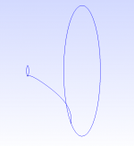
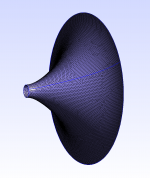
BTW, for anyone used to a different CAD, the imported model can be exported from Fusion 360 to IGES or STEP format. I tried to export IGES file and open it in Gmsh and mesh it, it works smoothly (this shape goes from circle to circle through an ellipse) -
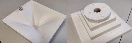
This mould could be milled on CNC from styrofoam (XPS) easily and quite cheaply I guess. Then laminated with a thin layer of fine fiberglass for a smooth surface.
This mould could be milled on CNC from styrofoam (XPS) easily and quite cheaply I guess. Then laminated with a thin layer of fine fiberglass for a smooth surface.
Attachments

Last edited:
I have been refreshing this thread frequently since started as I am quite excited about seeing possible construction techniques!
Bill
Bill
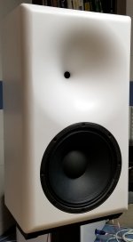
I recently completed a speaker that I suppose would fit here even though I didn't actually use Ath4 (I wrote my own tooling). The waveguide profile is OS with an angle- and curvature-matched Euler spiral (a.k.a. clothoid) termination starting at 40% of the total depth. Throat angle is 10°, which matches the compression driver I'm using (Celestion CDX1-1747). Here's the completed speaker:

The cabinet is 73cm x 41cm x 30cm (approx. 29in x 16in x 12in).
It took me a while to figure out how to make an accurate waveguide of this size since I don't have a big lathe or CNC router. I have a 3d printer, but I wasn't too keen on the idea of printing the whole waveguide due to the time required and the fact that the finished product would be a bit flimsy unless a lot of material was used. The basic process I arrived at is gypsum cement (basically plaster of paris, but much harder and stronger) over an MDF substrate coated with a suitable bonding agent. After some experimentation I found that type II water resistant yellow (carpenter's) PVA glue works remarkably well as the bonding agent (more on this later).
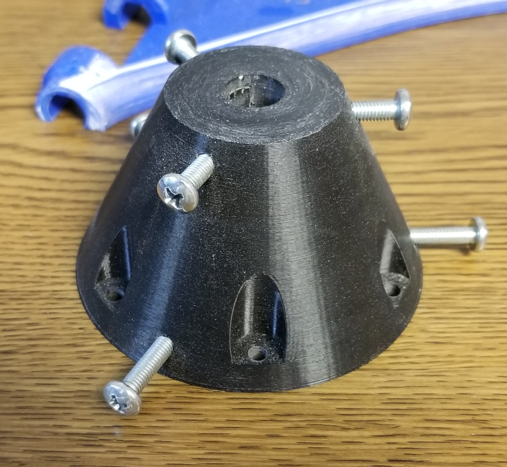
I shaped the gypsum cement using 3d-printed running molds that pivot on a 1/2in stainless steel rod held in place by this jig (which is also 3d-printed):
Here are the templates:
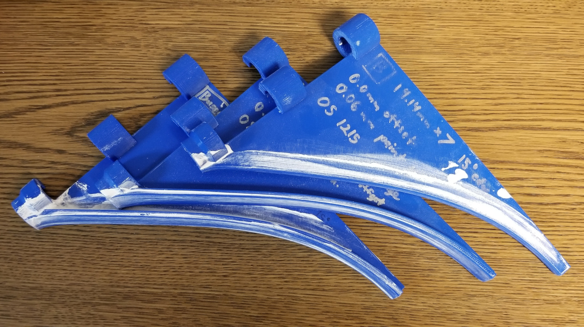
Two of the templates have a wide angled edge which helps to spread the plaster, kind of like a plasterer's trowel:

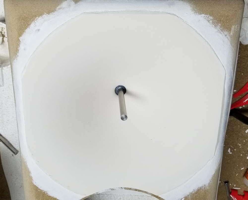
I applied the plaster in two coats, similar to two coat veneer plaster. The basecoat is about 3mm thick, cut 50/50 by weight with fine silica sand and the finish coat is 1mm neat. Here's the bare plaster waveguide. You can see the stainless rod in the middle:
This particular one was actually a failed attempt as the plaster didn't bond properly to the substrate. Due to the fact that gypsum plaster expands slightly as it sets, you need a bonding agent that provides some bond strength even when damp to prevent the plaster layer from lifting off the substrate near the waveguide mouth. For the attempt above, I sealed the MDF with a waterproof primer and then coated that with Elmer's Glue-All (a white PVA glue without water resistance). The problem is that the Glue-all turns back into a PVA emulsion on contact with the wet plaster and thus has no bond strength until dry. What I found works well is two coats type II water resistant PVA (I used Gorilla wood glue (NOT the polyurethane stuff), but Titebond II or any other similar product should work just as well), sanded lightly between coats, and one coat of Elmer's Glue-All. The Glue-All is probably not required, but I figured it would improve the bond once dry. Type II PVA adhesives get a bit soft when exposed to water, but don't completely re-emulsify. This property appears to be what makes it work so well for this application.
The gypsum cement I used is a G-P product called Densite (K-5, I think), which you can buy in small quantities at dickblick.com. USG Hydrocal White should also work well. Do not use USG Ultracal 30 or any other gypsum cement with portland cement (check the SDS). Based on my experience with Ultracal 30, it will shrink slightly over time and crack.
So how does the final product measure? Very well, in fact. The data seems to agree pretty well with the ABEC3 simulations I did. The measurements were done inside with a short gate, so I'd ignore below 1kHz for the most part.

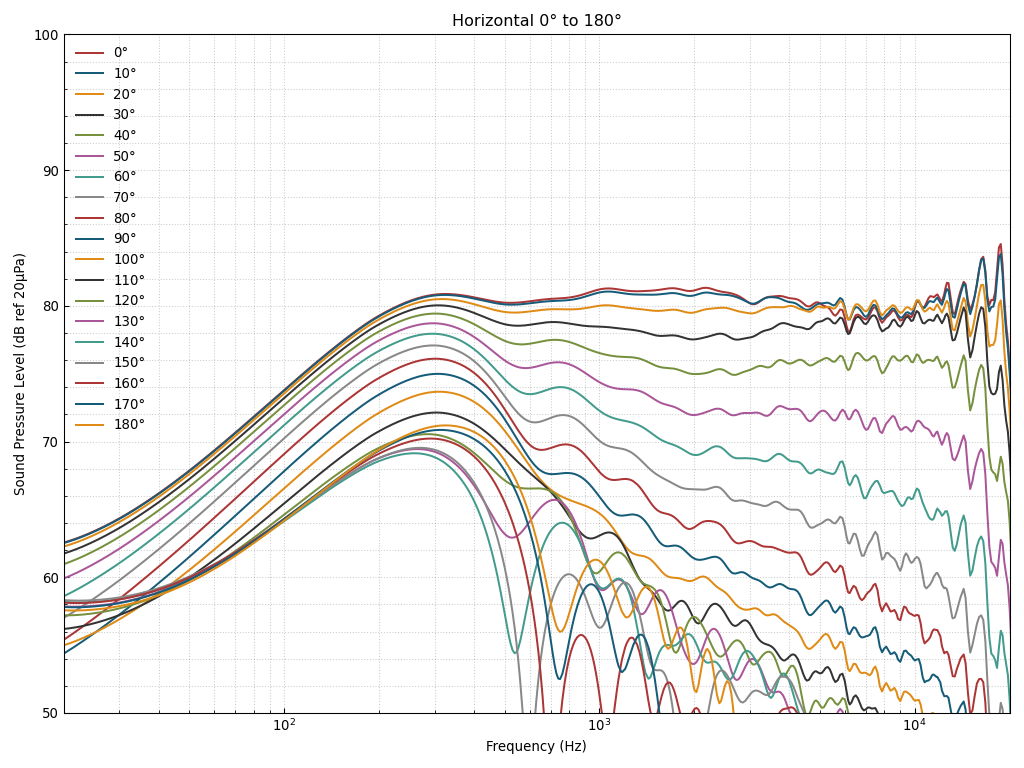
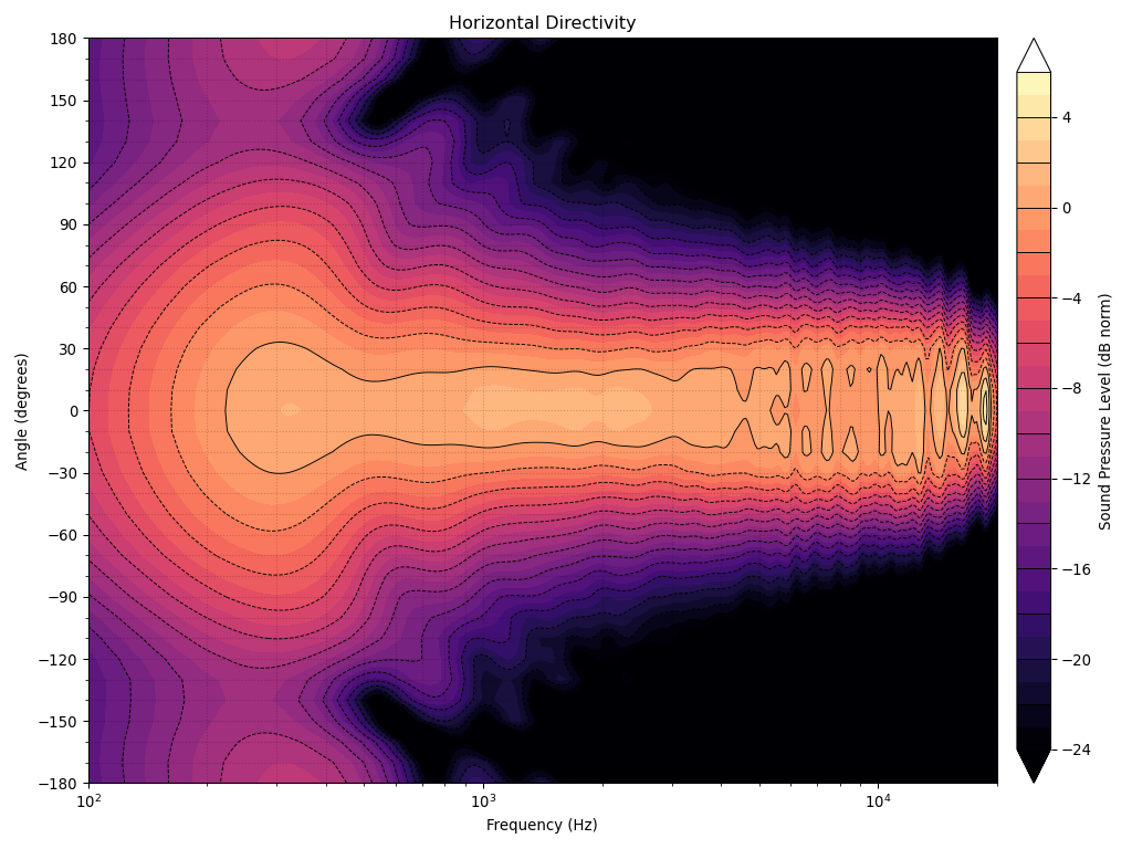
You can see that the sound power is very flat from the crossover frequency (1050Hz) to about 16kHz. Also, the 0° response is about ±1dB from the listening axis (18°), which I'd say is pretty good for an axisymmetric device. I think that this is pretty good evidence that mabat is right about how important the termination is. The axial response could be improved further with a more gradual termination, but the DI would be more tilted. I don't know which would be better in terms of perceived sound quality.
The cabinet is 73cm x 41cm x 30cm (approx. 29in x 16in x 12in).
It took me a while to figure out how to make an accurate waveguide of this size since I don't have a big lathe or CNC router. I have a 3d printer, but I wasn't too keen on the idea of printing the whole waveguide due to the time required and the fact that the finished product would be a bit flimsy unless a lot of material was used. The basic process I arrived at is gypsum cement (basically plaster of paris, but much harder and stronger) over an MDF substrate coated with a suitable bonding agent. After some experimentation I found that type II water resistant yellow (carpenter's) PVA glue works remarkably well as the bonding agent (more on this later).
I shaped the gypsum cement using 3d-printed running molds that pivot on a 1/2in stainless steel rod held in place by this jig (which is also 3d-printed):
Here are the templates:
Two of the templates have a wide angled edge which helps to spread the plaster, kind of like a plasterer's trowel:
I applied the plaster in two coats, similar to two coat veneer plaster. The basecoat is about 3mm thick, cut 50/50 by weight with fine silica sand and the finish coat is 1mm neat. Here's the bare plaster waveguide. You can see the stainless rod in the middle:
This particular one was actually a failed attempt as the plaster didn't bond properly to the substrate. Due to the fact that gypsum plaster expands slightly as it sets, you need a bonding agent that provides some bond strength even when damp to prevent the plaster layer from lifting off the substrate near the waveguide mouth. For the attempt above, I sealed the MDF with a waterproof primer and then coated that with Elmer's Glue-All (a white PVA glue without water resistance). The problem is that the Glue-all turns back into a PVA emulsion on contact with the wet plaster and thus has no bond strength until dry. What I found works well is two coats type II water resistant PVA (I used Gorilla wood glue (NOT the polyurethane stuff), but Titebond II or any other similar product should work just as well), sanded lightly between coats, and one coat of Elmer's Glue-All. The Glue-All is probably not required, but I figured it would improve the bond once dry. Type II PVA adhesives get a bit soft when exposed to water, but don't completely re-emulsify. This property appears to be what makes it work so well for this application.
The gypsum cement I used is a G-P product called Densite (K-5, I think), which you can buy in small quantities at dickblick.com. USG Hydrocal White should also work well. Do not use USG Ultracal 30 or any other gypsum cement with portland cement (check the SDS). Based on my experience with Ultracal 30, it will shrink slightly over time and crack.
So how does the final product measure? Very well, in fact. The data seems to agree pretty well with the ABEC3 simulations I did. The measurements were done inside with a short gate, so I'd ignore below 1kHz for the most part.
You can see that the sound power is very flat from the crossover frequency (1050Hz) to about 16kHz. Also, the 0° response is about ±1dB from the listening axis (18°), which I'd say is pretty good for an axisymmetric device. I think that this is pretty good evidence that mabat is right about how important the termination is. The axial response could be improved further with a more gradual termination, but the DI would be more tilted. I don't know which would be better in terms of perceived sound quality.
Attachments
-
 directivity_h_pos.png346.4 KB · Views: 5,187
 -
 directivity.png125.5 KB · Views: 5,280
 -
 template_detail.jpg321.8 KB · Views: 5,326
 -
 plaster.jpg187.8 KB · Views: 5,711
 -
 templates.jpg447.4 KB · Views: 5,804
 -
 jig.jpg404.5 KB · Views: 5,381
 -
 finished_speaker.jpg211.2 KB · Views: 6,113
 -
 directivity_contour_h.png369.6 KB · Views: 5,127
Big thumbs up for a stunning result!
It looks like a factory built loudspeaker and those plots are excellent.
Thank you also for your detailed description of the construction, a source of inspiration for other forum members.
The woofer is an Eminence, judged by the cone and surround?
What's is your (initial) subjective impression of the speaker(s) in the room?
Last edited:
WOW !
I am jealous about your skills ! It's just beautifull. Have class, because it's not glossy. We share similar looking tastes Bmc0...
The mid seems a 10". Why did you choose (and many diyers) a compression driver for the horned uppermid/tweeter instead a classic dome driver which can benefits of the horn reenforcment and perhaps more linear that a compressiopn driver ? Am I wrong to prefer classic driver if I would like to horn as well ? (home listening level, no pro studio related).
@ Mabat : thank you for the impressive work and sharing. Gave me the envy to draw my first horn 🙂 (and also the huge pedagogic efforts of Dr E. Geddes, Ro808, Docali and others fellows I forget the name right now)
Last edited:
In fact I would like to try a classic dome tweeter in such a waveguide some day. As I showed several times, in a similiar waveguide with a simple conical throat the performace should be pretty good actually, even with a biggish tweeter. Probably nowhere near the dynamics of a compression driver but I can't say how big that would be a problem at home listening levels. Maybe not so big.
I'm thinking about SEAS Excel T35C002. I would use BlieSMa T34B-4 right away but that's already somewhat costly.
So in the end, compression drivers are actually fairly cheap for what they can do.
I'm thinking about SEAS Excel T35C002. I would use BlieSMa T34B-4 right away but that's already somewhat costly.
So in the end, compression drivers are actually fairly cheap for what they can do.
- Home
- Loudspeakers
- Multi-Way
- Acoustic Horn Design - The Practical Way