Others are also trying 😉
https://audioxpress.com/article/dev...cal-investigation-of-an-unusually-shaped-horn
//
https://audioxpress.com/article/dev...cal-investigation-of-an-unusually-shaped-horn
//

Mabat, if you try to divide 1 by your gated measurement IR and and save the first 100-ish samples as a FIR filter, you'll really like the result!Yes. Could be further optimized I guess, this was just how I was able to set it up quickly manually.
Ok, you'll also have to multiply it by a high pass filter 🙂
Pixel perfect frequency response.
I believe the FA123 takes in FIR filters.

Last edited:
That's neat - I just tried that - but got some strange clipping which I could not get rid of despite settings - would hypos care to show the more exact steps please?
//
//
I believe the FA123 takes in FIR filters.
Only the later production batches from 2023 that accept firmware 5.7 and higher.
There are a few things to consider.
I use sigma studio which only accepts fir filters in text form, so I use HOLMImpulse to do the last bit.
You have to make sure you are always below 0db on all your filters and measurements.
This means that sometimes you have to shift things down.
Also gate your measurements and make sure you have enough reflection free space around your horn.
For most of us dealing with 800Hz - 20k a normal room will do.
Here is what I'll do to get a 300 tap fir filter using available tools.
1. Measure your horn with REW
2. Go to "IR Windows" and do 5ms on both the left and right side. Apply.
3. Go to "SPL and Phase" tab and select "Actions". Then Scale FR peak to 0 and Apply.
4. Click on the "ALL SPL" tab and your Actions should update, Choose "Trace arithmetic"
5. Under A, select your measurement and then select 1/A.
For starters go with 800hz lower limit, 24000 higher limit (considering you are sampling at 48kHz)
Target level depends on how uneven your response is. Start at -15 and play around until happy.
6. Press "Generate", a curve that is the mirror of your FR should appear
7. Get the filter that you generated in rePhase or use this one 24 LR 800hz filter
8. Open the Trace arithmetic again and multiply the filter with your 1/A curve. There is your filter.
9. Export 300 samples in total as a .wav, the center being at sample 150. (you can also make asymmetric filters if you know why)
10. Fire up Audacity and open the file. Does it look like an impulse?
Maybe you want to fade the start and the ending - this will change the response a bit
You can also apply a window to your filter before exporting from REW. 150 samples is close to 3ms at 48khz
11. If you need the filter to be ascii formated text document with coefficients,
then you can export the impulse as text in REW and import in HOLM Impulse.
12. In holm you can do another sweep of your horn and multiply it with the filter
to see if it becomes flat before you upload it to your dsp. Uploading jibberish fir filters is dangerous.
Always open the text file and make sure there are no values above 1
This is about it. I'm sure there are better and easier ways to do this, but it's a start.
This can virtually be a straight line if you use a longer filter and take your time to adjust the parameters
The good news is that it fixes things up in time domain and thus the phase curve.
The bad news is that it might not be super useful in your crossover.
More good news is that you can add a desired phase shift in rePhase when you design your high pass filter.
Well, you can also do measurements at 0, 5 and 10 degrees and average that (mind the center of rotation) to make a filter.
Then you will have a horn that integrates well with your woofer 🙂
This is to be stressed. At this point I can get only about 4.5 ms reflection-free time in my room, and it's already clear that this is not enough to get a reliable measured response below 1 kHz. To be able to design proper filters (without too big errors), I would need to wait for an outdoor measurement or go to a local community hall.Also gate your measurements and make sure you have enough reflection free space around your horn.
Ok, so this was what I didn't get as using the up/down arrows didn't indicate that - values where possible - but it was typing it in... now it works - thanks!Start at -15 a
//
I've had very good luck with Audiolense. It does a lot of the heavy lifting.
https://juicehifi.com
Alternatively, let BacchDSP sort everything out in one fell swoop...
https://www.theoretica.us/bacch4mac/
https://juicehifi.com
Alternatively, let BacchDSP sort everything out in one fell swoop...
https://www.theoretica.us/bacch4mac/
Or Acourate...
https://www.audiovero.de/home.php
Maybe the most universal solution. I use it since years ans still a lot to learn. It can do everything...as long as the user knows how to do it.
https://www.audiovero.de/home.php
Maybe the most universal solution. I use it since years ans still a lot to learn. It can do everything...as long as the user knows how to do it.
CamillaDSP can be an option for those stuck with the old FusionAmps like me, if you mainly listen from a digital source. CamillaDSP for piCorePlayer and FIR filters can be apllied with a convolver file.
Frankly, I'm not sure this last bit of "pixel flattening" is really necessary, or even desirable. One needs to be careful to "correct" only the part that is common to the whole radiation pattern (i.e. deep inside the horn/driver), otherwise I don't believe it actually helps. EQing anything else would be counter-productive, IMO. And what about the long-time stability?
cool with guide of how to use FIR.
I guess FIR is somehow similar to autotune. I have yet to hear and be fully convinced, that in normal situations, FIR is better than IIR / Passive Crossover.
I guess FIR is somehow similar to autotune. I have yet to hear and be fully convinced, that in normal situations, FIR is better than IIR / Passive Crossover.
When it is a procedure as simple as calculating a differential correction curve from data that is simple to generate, reducing linear distortion on the reference axis should be beneficial.
But I would suggest to linearize five angles, 0, + and -5 around the reference axis hor/ver. And this would then be weighted with LW and SP curve for tonality in a second step.
FIR wont do anything perceptible over IIR within the passband of the compression driver, but it takes more PEQs than readily available with the DSP-amps that we currently have, to fully linearize the response.
Bruno Putzey and Eelco Grimm’s train wreck poetics on the issue of brute force correction: https://www.grimmaudio.com/wordpress/wp-content/uploads/speakers.pdf
Hi everyone,
First off, a big thank-you to mabat for his excellent Ath software!
I’m planning to build an MEH around the DCX464 and asked @Olombo for his 3D scans of the driver. I then processed those scans so they can be used for ABEC or Akabak simulations—at least for the HF section.
I first aligned the scan of the central thorn with the DCX464 scan, and then I took advantage of their rotational symmetry. I plotted the distance of all points of the meshes against the driver’s central axis and fitted splines into the data to retrieve the contours of both the DCX464 housing and the thorn. Afterward, I sampled these splines and saved the data as two CSV files: dcx464_profileV2.csv and thorn_profileV2.csv. I’m attaching all of this in case anyone wants to explore it further.
For my own simulations, I imported the CSV files, along with the profile of an Ath waveguide, into LibreCAD. I drew in the missing components like the diaphragm and relevant interfaces, then saved it all as a .dxf file that can be loaded into Akabak in circSym mode.
I hope this proves helpful to anyone looking to design an Ath horn for the DCX or to modify its internal waveguide.
Raw scans:


Aligned scans:

Fitted splines:

Acoustic axis of the wave guide and plot of the area vs the distance from the HF throat:


First off, a big thank-you to mabat for his excellent Ath software!
I’m planning to build an MEH around the DCX464 and asked @Olombo for his 3D scans of the driver. I then processed those scans so they can be used for ABEC or Akabak simulations—at least for the HF section.
I first aligned the scan of the central thorn with the DCX464 scan, and then I took advantage of their rotational symmetry. I plotted the distance of all points of the meshes against the driver’s central axis and fitted splines into the data to retrieve the contours of both the DCX464 housing and the thorn. Afterward, I sampled these splines and saved the data as two CSV files: dcx464_profileV2.csv and thorn_profileV2.csv. I’m attaching all of this in case anyone wants to explore it further.
For my own simulations, I imported the CSV files, along with the profile of an Ath waveguide, into LibreCAD. I drew in the missing components like the diaphragm and relevant interfaces, then saved it all as a .dxf file that can be loaded into Akabak in circSym mode.
I hope this proves helpful to anyone looking to design an Ath horn for the DCX or to modify its internal waveguide.
Raw scans:
Aligned scans:
Fitted splines:
Acoustic axis of the wave guide and plot of the area vs the distance from the HF throat:
Attachments
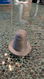
Really nice fit! Almost as if you had some good dimensions to work from. I took your idea for a sanding guide plug thingy which made the sanding task super easy.So, could someone confirm this will fit the BMS 4552?
STL file: https://at-horns.eu/ext/BMS4552-plug.zip
View attachment 1397095
(Sanding down the tip is necessary.)
So will this adapter simply work in the 4554 long adapter on a A460G2?
I need to tune the first layer on my printer.cfg but I will be pretty interested in how this combo works.
Attachments

Thank you for doing those measurements! I took your profile curves and made a 3D model as a STEP file that's a little easier to work with for those who are interested.
It is attached. I can also provide other file formats if anyone is interested (I'm working in Rhino 3D).

Looks like the throat exit is 0º.
It is attached. I can also provide other file formats if anyone is interested (I'm working in Rhino 3D).
Looks like the throat exit is 0º.
Hi everyone,
First off, a big thank-you to mabat for his excellent Ath software!
I’m planning to build an MEH around the DCX464 and asked @Olombo for his 3D scans of the driver. I then processed those scans so they can be used for ABEC or Akabak simulations—at least for the HF section.
I first aligned the scan of the central thorn with the DCX464 scan, and then I took advantage of their rotational symmetry. I plotted the distance of all points of the meshes against the driver’s central axis and fitted splines into the data to retrieve the contours of both the DCX464 housing and the thorn. Afterward, I sampled these splines and saved the data as two CSV files: dcx464_profileV2.csv and thorn_profileV2.csv. I’m attaching all of this in case anyone wants to explore it further.
For my own simulations, I imported the CSV files, along with the profile of an Ath waveguide, into LibreCAD. I drew in the missing components like the diaphragm and relevant interfaces, then saved it all as a .dxf file that can be loaded into Akabak in circSym mode.
I hope this proves helpful to anyone looking to design an Ath horn for the DCX or to modify its internal waveguide.
Raw scans:
View attachment 1398284View attachment 1398283
Aligned scans:
View attachment 1398285
Fitted splines:
View attachment 1398286
Acoustic axis of the wave guide and plot of the area vs the distance from the HF throat:View attachment 1398287View attachment 1398291
Attachments
- Home
- Loudspeakers
- Multi-Way
- Acoustic Horn Design – The Easy Way (Ath4)