Yes, I do. On the contrary, I think it could help to reduce the exposition of the waveguide to the sound radiated from the driver below. The sound from the opposite sides of the woofer diaphragm should cancel out (to some degree) in that direction. Isn't that the case?
Last edited:
Yeah thats the logic, at least in theory the waveguide would be ~null of dipole woofer and have very little effect on woofers response. Other benefit is DI of such "dipole" kind of radiation is relatively high, similar to waveguide, but polar patterns differ. Benefit of this is that there shouldn't bee too much of a DI dip around crossover as interference (lobing) on the crossover is not so intense due to difference in pattern. Although, the system DI is perhaps smooth both vertical and horizontal coverage has more or less wiggle to off-axis angles as polar patterns are not alike.
If you add damping to the back the null turns >90deg angles from dipole to cardioidish and waveguide is not at woofers side null anymore. Also polar patterns get more alike which means smoother response to any horizontal off-axis angle but also interfence is now stronger as patterns get closer to each other and you get more DI peak / power dip around crossover.
To really overcome all this make full range dipole speaker. Or, the woofer would need to be inside the waveguide, MEH. Also fullrange driver line array kind of overcomes this by having same interference on all of the drivers, same physical structure, same immediate acoustic environment for all drivers. Its impossible to get rid of all interference as long as we need to have physical objects so just matter of picking the poison. Sound injected directly to brain?")
If you add damping to the back the null turns >90deg angles from dipole to cardioidish and waveguide is not at woofers side null anymore. Also polar patterns get more alike which means smoother response to any horizontal off-axis angle but also interfence is now stronger as patterns get closer to each other and you get more DI peak / power dip around crossover.
To really overcome all this make full range dipole speaker. Or, the woofer would need to be inside the waveguide, MEH. Also fullrange driver line array kind of overcomes this by having same interference on all of the drivers, same physical structure, same immediate acoustic environment for all drivers. Its impossible to get rid of all interference as long as we need to have physical objects so just matter of picking the poison. Sound injected directly to brain?
Last edited:
Yep.Yeah thats the logic, at least in theory the waveguide would be ~null of dipole woofer and have very little effect on woofers response.
(3dB step)
Last edited:
Yeah, again all relative to wavelength, top of the woofer bandwidth (below beaming of course) would reflect and diffract most as waveguide size is relatively big to wavelength. Also if waveguide is bit higher up, which might be good for DI hump anyway, the reflection related interference would be reduced in amplitude and moved lower in bandwidth as path length (difference) gets longer, no matter what pattern.
Not sure if the dipole null works as well as intuition says, because the null is result of front and back sounds interfering. Now when there is (asymmetric) waveguide there as disturbing object, backside shape of the waveguide being different than the front side, some reflection and diffraction would happen. On the shorter wavelength at least. Perhaps it works just fine, can you sim it?
Its impossible to have two objects, woofer and waveguide, so that they wouldn't affect each others response at least some. As they are very different objects they have different effect on each others response and probably is one reason why crossover would be audible. Even if both used ideal transducers their "acoustic fingerprint" would be different. Not sure if any of it is audible, but intuitively two different sounds don't fuse into one as well as two identical sounds. I would think that on a MEH the "fingerprint" would be same for full range bandwidth and perhaps helps make such speaker sounding more coherent one, even though it is a multiway speaker and there is some added interference from diffraction and all that it would sound like one.
Well, perhaps all we can do is just minimize the difference, reduce all kinds of reflections and diffraction if its possible without bad trade-off. All we need to do is fool the hearing system as well as we can, right?
Last edited:
... this is only loosely related, but I'm investigating the scenario of a small synergy cardioid horn.
I have alredy made the sealed box and about to simulate the position/size of the ports of interest to deepen the directivity.
This box is not to be used lower than 200hz, so I won't loose that much output by cardiod porting it.

These are the measurements of the box (roughly EQ'd "flat")
The directivity plot is normalized on axis.


Because of the geometry, I've got to do a bit of work dividing the domains to be able to simulate it properly so I won't have the simulations ready today.
What are your thoughts?...apart from that the horns needs a bit of work
I have alredy made the sealed box and about to simulate the position/size of the ports of interest to deepen the directivity.
This box is not to be used lower than 200hz, so I won't loose that much output by cardiod porting it.
These are the measurements of the box (roughly EQ'd "flat")
The directivity plot is normalized on axis.
Because of the geometry, I've got to do a bit of work dividing the domains to be able to simulate it properly so I won't have the simulations ready today.
What are your thoughts?...apart from that the horns needs a bit of work
Attachments
so you are modeling that as dipole woofer rather than sealed with resistance vent?
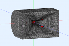
Well, it's both. I hoped it would be clear from the picture (?):so you are modeling that as dipole woofer rather than sealed with resistance vent?
https://www.diyaudio.com/community/...-design-the-easy-way-ath4.338806/post-7240796
yeah go ahead, I feel it should work!... this is only loosely related, but I'm investigating the scenario of a small synergy cardioid horn.
I have alredy made the sealed box and about to simulate the position/size of the ports of interest to deepen the directivity.
This box is not to be used lower than 200hz, so I won't loose that much output by cardiod porting it.
View attachment 1132504
These are the measurements of the box (roughly EQ'd "flat")
The directivity plot is normalized on axis.
View attachment 1132506 View attachment 1132512
Because of the geometry, I've got to do a bit of work dividing the domains to be able to simulate it properly so I won't have the simulations ready today.
What are your thoughts?...apart from that the horns needs a bit of work
Internal volume and (side) aperture size makes acoustic low pass filter which might need tuning, either by adjusting volume inside or the aperture. You could make the side panels detachable to experiment with various sized apertures (and distance from front edge). Use melamine foam (magic sponge) inside/at the aperture, seems to work fine. Acoustic low pass makes group delay which makes the pattern happen.I don't think it can be both; I think it ends up in between. Increased resistance improves the cardioid effect at expense of the dipole effect and vice versa. I've modelled this to death in Vituix. Its great to see an ABEC sim of the same/similar thing. It would be very interesting to me if you were to model side vents alone so we could see the difference.Well, it's both. I hoped it would be clear from the picture (?):
https://www.diyaudio.com/community/...-design-the-easy-way-ath4.338806/post-7240796
As a practical matter, I think leaning towards resistive side and away from dipole is better as it means less excursion on the woofer. I am modelling a Purifi PTT6.5 below an ST260 and it has just enough Xmax to provide cardioid response down to 100 Hz aiming for 105db SPL. As a dipole it wouldn't go down that low, but my system simulations look better if it does. If a vituix simulation of cardioid side vents is worth anything, it says you'll get a increased directivity upwards with side vents; you don't need the top vent for that.
With a waveguide body (-2dB back source).
View attachment 1132502 View attachment 1132505
View attachment 1132510 View attachment 1132513
Nice thanks for these!
On a quick look monopole and dipole configuration both seem to have about similar influence from the waveguide, so dipole null towards waveguide didn't make too much of a difference in this regard, some reflection and diffraction happens. There seems to be more difference when waveguide was pulled bit further out.
Counter intuitive in a way that the null wouldn't work, but its logical as also the dipole null consists of sound. There is sound towards the waveguide from the woofer in dipole configuration and the sound would reflect and diffract like sound does. Dipole source sound is cancelling to sides when there is nothing there to disrupt and sound from each side propagates together to same direction in opposite polarity.
Very interesting. I must take back from my previous posts that a fullrange dipole system would be most interference free (from other ways being there at each others nulls) as the nulls don't seem to happen as nice when there is an object to disrupt. Interference free source is only when there is no additional objects there nearby, another for MEH / coax
Last edited:
Yeah, until I saw the sims myself, it wasn't at all obvious to me that it behaves like this, as regards the dipole.
As for the MEH, I have yet to see results that would convince me to use it rather than a conventional setup (I'm not into PA).
- These are polars at 2m, a) for the LF enclosure only and b) with the waveguide body present above it:


Full horizontal (left - LF box only, right - including the WG):


Full vertical (left - LF box only, right - including the WG):


These differences are absolutely not worth considering, IMHO, given everything it does right.
As for the MEH, I have yet to see results that would convince me to use it rather than a conventional setup (I'm not into PA).
- These are polars at 2m, a) for the LF enclosure only and b) with the waveguide body present above it:
Full horizontal (left - LF box only, right - including the WG):
Full vertical (left - LF box only, right - including the WG):
These differences are absolutely not worth considering, IMHO, given everything it does right.
- Home
- Loudspeakers
- Multi-Way
- Acoustic Horn Design – The Easy Way (Ath4)