I suggest you move over to augerpro's waveguide thread for dome tweetersAny recommendations?
https://www.diyaudio.com/community/threads/open-source-waveguides-for-cnc-3d-printing.318190/
and augerpro's dedicated website: https://www.somasonus.net/waveguides

The truth is that I mentioned all of this at the moment I introduced the functionality
Yes I know and have worked with the config file accordingly for many months. Sometime in between the many last pre-releases, I mean that I had read that PaseComp was now obsolete and removed automatically, but I might have misunderstood something. I did not note that when I had removed the entry that the issue began, because I had little time and doing it all in-between other things.
Anyway, if it was just me misunderstanding the software this is superb, because this is an easy fix.
P. S.:
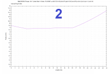
After the FRD appear to be without phase issue, I hope this VCad simulation holds true for crossover integration. A very nice integration with a 10 inch woofer at crossover, from SP, SPDI and PIR all considered:

.png")
.png")
I'm still working this rectangular horn for an AMT driver.
How can I get the mouth rollback to work on this? I've tried the different commands that have been used in this thread but it doesn't work on this rectangular horn. Where am I going wrong here:
How can I get the mouth rollback to work on this? I've tried the different commands that have been used in this thread but it doesn't work on this rectangular horn. Where am I going wrong here:
Code:
     NamePrefix = "array_ver"
  }
Inclination = 270
MapAngleRange = 0,180,72
NormAngle = 0
}

ABEC.SimType = 2
ABEC.f1 = 500
ABEC.f2 = 10000
Horn.Adapter = {
Height = 148
Segments = 0
Width = 37
}

Horn.Part:1 = {
H = {
a = 64.5
a0 = 5
k = 1
n = 4
q = 0.996
r0 = 74
s = 0.7
}

L = 1
Segments = 16
V = {
a = 26
a0 = 5
k = 1
n = 4
q = 0.996
r0 = 18.5
s = 0.7
}
}

HornGeometry = 2
Length = 100

Mesh.AngularSegments = 64
Mesh.InterfaceOffset = 0
Mesh.InterfaceResolution = 8
Mesh.MouthResolution = 10
Mesh.RearResolution = 25
Mesh.SubdomainSlices = -2
Mesh.ThroatResolution = 5
Mesh.WallThickness = 10
Mesh.ZMapElementSize = 0.3,0.6,0.5,0.95

Output.ABECProject = 1
Output.STL = 1Instead of independent "H=" and "V=" (which are OSSE definitions) use one single "D=" R-OSSE definition - that will become the profile of the diagonal. The only limitation is that it must be the last part of the horn. Together with the R-OSSE parameters, use "Inclination=" to set the inclination of the diagonal.I'm still working this rectangular horn for an AMT driver.
How can I get the mouth rollback to work on this?
I simulated it to try to understand why zero throat length is better.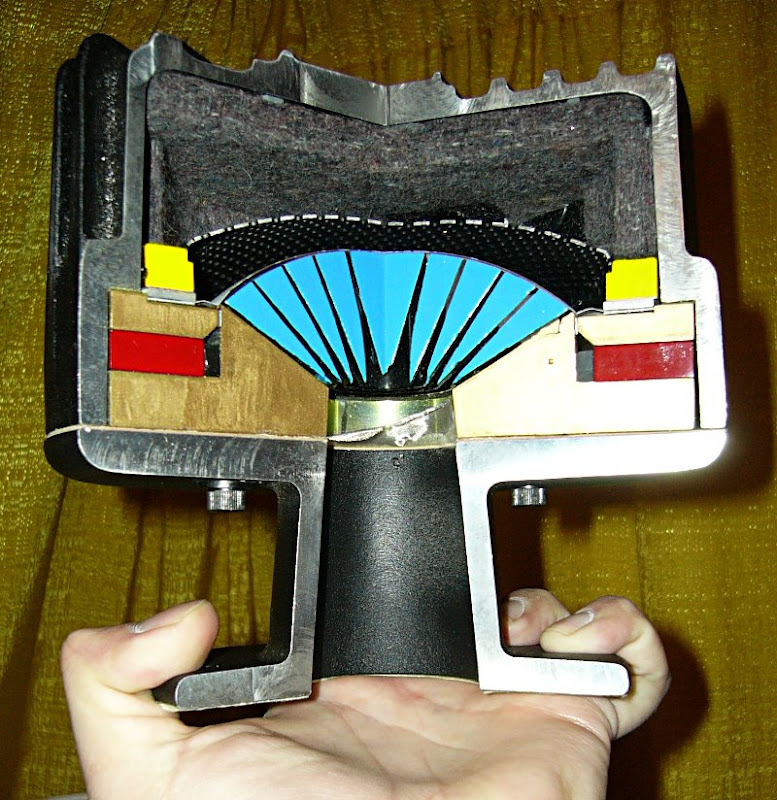
Are you intending to mill the compression driver so the exit is larger?
Or mask off part of the phase plug?
I'm just trying to figure out how you'll change the exit angle without doing that.
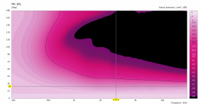
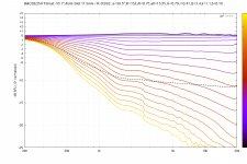
That's good news: directivity is better, higher order modes shifted higher in frequency, and bumps can be corrected with equalization. I have very little experience with compression drivers/horns so after learning that information my current intuition is to use impedance to boost the compression driver around 12kHz (based on my personal hearing limit). Then pull down all the frequencies below 12kHz to flatten frequency response.As the throat is made also effectively smaller (which is not a small thing), all the HOMs should shift higher in frequency (as I understant the matter) and I suspect that it's already high enough not to matter. You can also see that above 15 kHz the directivity issues went away. What remains is the reflection at the discontinuity and the wavy throat acoustic impedance, which corresponds to the frequency response "bumps" but these are readily correctable at the signal level.
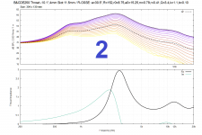
This Internal Ring shape supplies a small boost between 10-12kHz.
Attachments
I put the Fusion printable waveguide script on github: https://github.com/TomKamphuys/CreatePrintableWaveguide Any help is appreciated.
Current status:

Current status:
The back radiation attenuated by 3 and 6 dB:
.png")
.png")
I only wonder if that drop around 400 Hz can be real. Hard to believe.
I only wonder if that drop around 400 Hz can be real. Hard to believe.
What is the idea? Some kind op open baffle with back radiation absorbtion designed in?Just an idea
It's amazing how many new ideas pop up in your head, even after years of Ath. I admire your open mind. Many times you'll twist a weird idea, even ones you don't believe in, into a learning experience.
It's actually nothing new, the idea is to extend a narrowed directivity to lower frequencies - to increase the DI well across the lower midrange by utilizing the radiation of the back side of the diaphragm. Seems it should work pretty well. Would require a separate woofer though, making it a three-way. One (big?) advantage is that it can be quite small for what it can do.
Last edited:
It appears to be pretty sensitive to the placement of the opening. This is a bit further back.


Fortunatelly this is still only a relatively small model to solve, so it can be put into an optimizer loop.
Fortunatelly this is still only a relatively small model to solve, so it can be put into an optimizer loop.
Yeah 8" driver can make ~6db DI down to perhaps 200Hz, in ~20cm x 20cm x 10cm structure, not much bigger than the woofer itself. Cross it to ST260 ~1-2kHz and get ~6-10db DI from ~200-300Hz to top in relatively compact structure.

This is fairly high from 500 Hz. Now only to find a way to get rid of that sharp transition.


The cavity should be filled with damping (open-cell foam or something), otherwise there's a huge resonance.
(The acoustic impedance shown is for the front diaphragm only. The rear side looks very different...)
The cavity should be filled with damping (open-cell foam or something), otherwise there's a huge resonance.
(The acoustic impedance shown is for the front diaphragm only. The rear side looks very different...)
Last edited:
Thats the plan 🙂 and some other tweaks here and thereI would use a bit lower-DI waveguide in this case.
This would be nice but it's for "Damping=0.5" all around the enclosure 🙂
-3dB back radiation:

Equal sources:

-3dB back radiation:
Equal sources:
It reminds me of a waveguide with a lot of 'diffraction' from the edge. That also has an influence on DI and you see the same dip, albeit not as deep as the diffracted sound has a lower volume. Here the volumes are comparable resulting in a null.
I haven't done the math though...
I haven't done the math though...
This is for driving the front side of the diaphragm only - it must the cavity.
But again, this is still far from reality as there's absolutely no damping in the model (yet).


I could try to tilt the wall opposite to the back side of the diaphragm.
The better without a damping, the better with a damping. Or not?
But again, this is still far from reality as there's absolutely no damping in the model (yet).
I could try to tilt the wall opposite to the back side of the diaphragm.
The better without a damping, the better with a damping. Or not?
Last edited:
- Home
- Loudspeakers
- Multi-Way
- Acoustic Horn Design – The Easy Way (Ath4)