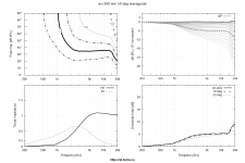
What I see is a pretty good match between the CircSym and 3D. It probably doesn't make much sense to try for a better detail than what you show anyway, so I would say you are safe to go with those data.
Maybe someone can reproduce it.
The fact that I have three different outputs for a circular device was most problematic. When CircSym and 3D additionally do give different coverage angles, it becomes a bit random. The reality can deviate from the model, but not the model from itself. At least if it is as simple.
The fact that I have three different outputs for a circular device was most problematic. When CircSym and 3D additionally do give different coverage angles, it becomes a bit random. The reality can deviate from the model, but not the model from itself. At least if it is as simple.
And are you sure all else is equal (center of rotation, etc).? It's not clear from the script excerpt. I think you already showed that the previous problem was only a presentation issue. The CircSym and 3D are different models so there simply can be a small difference.
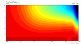
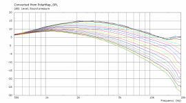
I have not changed anything apart from switching between 3D and CircSym (including switching the mesh frequency number, as per guide). The axes are different in both modes in VCAS, but not changed by command. Maybe the previous output difference between horizontal, vertical and diagonal is a presentation problem, but it gives me no clue which of the very different graphs is correct. Also, because there is relevant difference between 3D and CircSym, I cannot compare VCAS results with the ath reports to find the valid output.
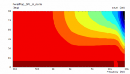
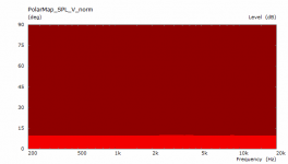
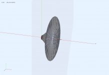
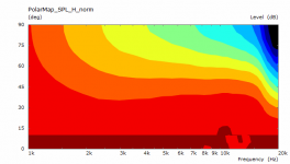
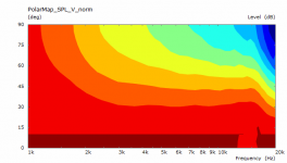
I have rerun it. The output of both models, CircSym and 3D, is indeed close, differing a bit in mid frequencies. Why is it then, that VCAS is giving this output? The waveguide in VCAS seems rotated. I want to compare asymmetric and axisymmetric devices and it would be helpful if axisymmetric output could be gauged in VCAS, maybe without running the slower 3D mode. The output is calculated from Ath beta 5, source is attached.
Regards
Regards
Attachments
-
 D_norm_3D.png7.9 KB · Views: 141
 -
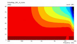 H_norm_3D.png7.8 KB · Views: 166
 -
 V_norm_3D.png8 KB · Views: 153
 -
 waveguide_3D.png41.4 KB · Views: 175
 -
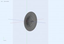
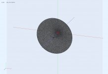 ABEC axes_3D.jpg96.5 KB · Views: 152
 -
waveguide_3D.cfg.txt1.7 KB · Views: 99
-
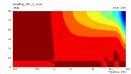 D_norm_circsym.png8 KB · Views: 146
 -
 H_norm_circsym.png7.8 KB · Views: 166
 -
 V_norm_circsym.png2.9 KB · Views: 142
 -
 waveguide_circsym.png41.6 KB · Views: 140
 -
 ABEC axes_circsym.jpg55.7 KB · Views: 127
 -
waveguide_circsym.cfg.txt1.7 KB · Views: 108
Post the actual ABEC projects that are created, perhaps there will be something more obvious that is different between them.I have rerun it. The output of both models, CircSym and 3D, is indeed close, differing a bit in mid frequencies. Why is it then, that VCAS is giving this output? The waveguide in VCAS seems rotated. I want to compare asymmetric and axisymmetric devices and it would be helpful if axisymmetric output could be gauged in VCAS, maybe without running the slower 3D mode. The output is calculated from Ath beta 5, source is attached.
Regards
You need to zip up the project folder, to have the meshes and other text files included 🙂Yes, the respective ABEC files (remove .txt from the file ending).
Mérde, now I have run other iterations and the mesh files changed. I have to upload them another day (night time Europe).
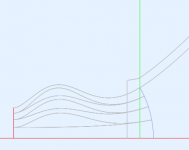
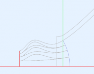
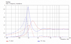
ESP - when the length is changed, throat impedance changes. The output wavefront and the resulting polar pattern stay virtually the same.
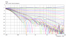
Here's a "long" vs "short" plug (no other parameters changed).
Here's a "long" vs "short" plug (no other parameters changed).
Attachments

The two horns were different. What I was interested checking was the 10khz dip which is evident in both cases.I would say that in this case the 4 vane version is actually quite good for a 2" driver. There is some HF axial ripple similar in both versions which may have something to do with the input wavefront shape, who knows. But why are the two versions so much different at midrange frequencies? Are these different horns or why do you think is that? It's probably not due to a different number of vanes.
I might build a little device like the one used to measure the berstis lens to measure what the wavefront produced by the axi-2050i actually is.
(long exposure picture of a microphone with a led diod on it powered by a gate that compares soundcard output and mic input)
As for the 10 kHz on-axis dip, it seems I can get a similar result when lowering driving weight of the central channel. Perhaps as an experiment you could try to dampen the outer plug channels a bit to see if that changes something.
I still think we could measure the real weights of the individual channels and then maybe adjust the geometry somehow. The problem is that this could be frequency dependent.
I still think we could measure the real weights of the individual channels and then maybe adjust the geometry somehow. The problem is that this could be frequency dependent.
Maybe making the center channel a bit bigger 🙄
I found a script that subdivides a circle with equal areas and got these values:
os0 = 0.5,0.707,0.866

I found a script that subdivides a circle with equal areas and got these values:
os0 = 0.5,0.707,0.866
Last edited:
If the input wavefront is not flat, it should have some effect, not because the areas are equal but because it will be a slightly different division. For a flat wavefront I haven't found out this to be relevant, provided the outer (bended) channels are narrow enough.
There's a little detail not handled yet - at the moment the output areas are calculated so that they are proportional to the input areas. What I neglected so far is the non-zero thickness of the vane tips. This changes the areas a bit and so the proportions will be different. I will take this into account in the next release. Maybe it's negligible, maybe not quite.
There's a little detail not handled yet - at the moment the output areas are calculated so that they are proportional to the input areas. What I neglected so far is the non-zero thickness of the vane tips. This changes the areas a bit and so the proportions will be different. I will take this into account in the next release. Maybe it's negligible, maybe not quite.
Last edited:
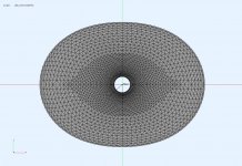
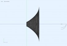
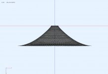
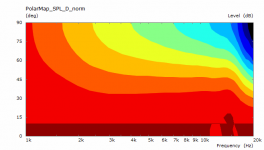
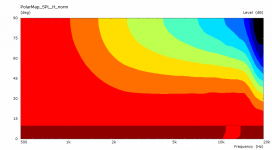
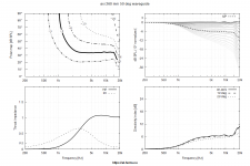
Documenting an asymmetric device which is 265 mm by 201, radiating 100 degree horizontal and 80 vertical.
Hard to say whether the increased C-C distance that is possible on a baffle outweights the detrimentel effect of a smaller vertical length.
Hard to say whether the increased C-C distance that is possible on a baffle outweights the detrimentel effect of a smaller vertical length.
Attachments
For comparison, the performance of the axisymmetrical variant, which does not allow a C-C spacing according to the teachings of Kimmo Saunisto:
Attachments
Did you mean decreased C-C distance? No it doesn't, IMHO, but what you show is only mildly asymmetrical anyway.Hard to say whether the increased C-C distance that is possible on a baffle outweights the detrimentel effect of a smaller vertical length.
Beware that the black&white report still shows only data for one chosen polar set. Hence it represents a full description only for an axisymmetric device but not for a general case (which needs to be sampled on the whole spherical surface surrounding it). That's something still missing in the tool as I somewhat lost interest in non-axisymmetric shapes at some point (which may change).
Last edited:
Increased. With a given baffle height and woofer diameter, in a two way system the vertical C-C can only be increased by decreasing the height of the waveguide.Did you mean decreased C-C distance? No it doesn't, IMHO, but what you show is only mildly asymmetrical anyway.
(Yes, I know, ath report does not represent sum of all axes)
- Home
- Loudspeakers
- Multi-Way
- Acoustic Horn Design – The Easy Way (Ath4)