- What we need now is a simple DIY procedure how to "fit" a compression driver model from a set of measurements.
VACS has a built-in tool for this, if you supply it with an electrical impedance measurement of a driver. Of course, the better the input data, the closer the result so measurements that are generated from lots of averages in a reflection-free environment are a good first step.
I did this recently for a project, using 48 measurements across 12 different samples of a 2” LaVoce driver. I generated a mean curve from that data, put it into VACS, and the fitting algorithm created a set of parameters for use in Akabak. They differed quite a bit from the published T/S parameters, but the resulting impedance curve matched much more closely.
There’s also that method for generating a two-port model of a driver, using electrical impedance and current measurements done with a hard floor and a simple known horn geometry as terminations. That would represent it in some detail. I’m not sure how that could be used in ABEC/Akabak as it stands though. Perhaps a custom .dll and the ‘script’ element in the LEM section?
Sorry for the double post, but it might be useful to show the VACS method, as it's a little buried.
Some screenshots are attached. In order they are:
Hope that helps 🙂
- Take the electrical impedance measurements. DATS, REW and ARTA all work well
- Import the electrical impedance traces into VACS
- Generate the mean curve under Processing > Trend Analysis. You might also want to check the Std Error to spot or exclude outliers
- Select the mean curve and copy it with Ctrl+C or Edit > Copy
- Open a new Dyn Drv Parameters form under File > New Graphs, editors etc > Special forms
- Paste the mean curve into the Dyn Drv Param form
- Type in the T/S parameters from the driver spec sheet into the relevant Value fields on the right side of the screen
- Check one of the red coloured options for Bl, Mms, Cms or Rms to enter that data, which then calculates the other values
- Be careful to use the correct units! It helps to type the unit value after the number, especially for Le and Mms.
- Choose a VC Model value; it's a drop down menu but doesn't look like one. The different options are explained in the ABEC or VACS help files.
- Click the Start button to put in a starting point Model Impedance curve
- Check the Opt boxes to choose which parameters to optimise to fit the measured mean curve more closely
- Click Start again and give it a moment, when it doesn't appear to be making more improvements, click Stop.
- Rinse and repeat until both the Real and Imaginary curves for the Model Impedance are close to the measurement
- This can also generate the Klippel or VACS curve model data such as ExpoRe, ExpoLe, Re2 and Le2 for a more accurate simulation
- Export the data from VACS
- If you can't save the curve in the demo version, then there's the option to copy the values as pre-configured ABEC/Akabak formula values for use on a Dyn Driver element in the LEM section of the sim
Some screenshots are attached. In order they are:
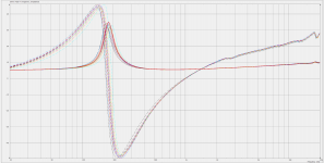
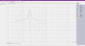
- Some example data, including a generated mean curve
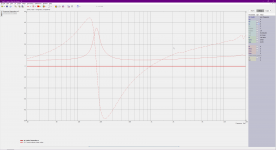
- The initial view of the form with mean complex values pasted in
- The curve generated by inputting the T/S parameters from the spec sheet
- The result of model fitting after ~30 seconds of computation, using the Klippel+Akabak VC model option
Hope that helps 🙂
Attachments

That technique won't work for a compression driver because it is a coupled resonant system, i.e. two peaks, like a ported enclosure. Also, you are assuming that the published TS specs are correct. It takes a perturbation to nail down all the parameters as measured and not input. With a compression driver it takes two perturbations to nail down all the parameters. One is convenient and that is closed off throat, but then you doo need to know the volume of the throat ahead of the diaphragm. The other a "known" waveguide is not as easy as you need to know the exact load of the waveguide. Not too hard to simulate, but not easy to actually measure.
What about a vacuum chamber? Would that help in estimating at least the mechanical parameters of the resonant system?
Otherwise I think it wouldn't be very hard to simulate it with the the closed off throat. And to perturbate the paramaters to find a match to the measured impedance (?).
Otherwise I think it wouldn't be very hard to simulate it with the the closed off throat. And to perturbate the paramaters to find a match to the measured impedance (?).
That technique won't work for a compression driver because it is a coupled resonant system, i.e. two peaks, like a ported enclosure. Also, you are assuming that the published TS specs are correct. It takes a perturbation to nail down all the parameters as measured and not input. With a compression driver it takes two perturbations to nail down all the parameters. One is convenient and that is closed off throat, but then you doo need to know the volume of the throat ahead of the diaphragm. The other a "known" waveguide is not as easy as you need to know the exact load of the waveguide. Not too hard to simulate, but not easy to actually measure.
Sure, that's why I suggested the other method for compression drivers. A vacuum chamber is the preferred option for the second measurement in that method, but I doubt many people have access to one of a suitable size? The nice thing about the 'known load' option is that it should be possible to generate a simple waveguide BEM simulation and CAD file that could be easily 3D printed to fulfil that aspect. At the very least, for a given range of frequencies.
For the VACS method with cone drivers, the published parameters aren't assumed to be correct. That's kind of the point, and you can see how far off the published specs are from a mean measurement in the third screenshot. It's doing curve fitting to a measured electrical impedance. I could technically put any values in to start off, but the algorithm would take longer to get a good result in relation to the measurement.
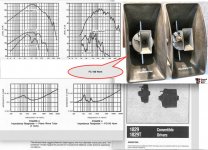
The old 60 watt Electrovoice (University Sound) 1829 "Convertible" driver used both sides of the diaphragm, one side loading into a re-entrant (folded) horn, the other high frequency side coupled to a small high frequency diffraction horn.Something like a bass-reflex enclosure for a compression driver? 🙂
You would have to utilize that power somehow in the net "forward" radiation... I've never thought about that. Hard to imagine.
I suspect the "tweeter" side has a simple phase plug, and the rear side is just a band-pass chamber. Many EV1829 drivers were used with a plastic cap covering the rear threads on various single entry thread-on straight or re-entrant horns.
They actually sounded pretty good for PA use in the cafeteria and gymnasium 50 years ago (compared to my memory of the vocal range of Altec 511/A7 "Voice of the Theater cabinets...), it would be interesting to hear them equalized flat from 2 or 300-16kHz, especially using a OS type horn for the HF.
Art
Attachments
Last edited:
Ah increased loading on the backside should be utilized in the front somehow? This would require modifications to the front (reflex port to the waveguide) and probably ruin it.
Most ideas are already found out decades ago so probably my ideas are in vain, but it is so much fun can't help posting 😀
Maybe its not possible to make a net gain on the front but perhaps limiting the excursion will have positive effect on distorsion in the low end and in the low stop band. Manipulating the driver side is to only affect the primary of a transformer - to add load, one need to change the "turns ratio" for the particular frequency in mind...
//
Last edited:
^Sounds reasonable, unless the trade-offs were bad for performance, I have no idea what would those be but there is always something. Considering what is available commercially should be best there is. Many companies have developed drivers for a long time and still no magic bullets, more different models available than ever. They might be optimized for different application/market though... 🙂 Anyone offering coaxial compression drivers for 1" throat?
Anyway, it really looks like the loading aspect would be on the driver/phaseplug and not on the waveguide. And actually, I don't know if it would be even required other than to get more SPL. I mean the waveguide/driver has to be crossed over to the next device at some frequency anyway and if one cares about acoustic pattern the mouth size comes into play and dictates the xo, not the loading. It would be nice to have extra juice down low, but then one would have to welcome some trade-off like always. And there is no need to in this case really because we got what we needed, the very smooth pattern control, right? Really good his are now achievable, but rest of the system is still missing 🙂
Anyone experimented with ATH script for cone drivers, for mid range duty? I remember mabat posted some 3D models maybe last year, not sure if there was any sims associated? Maybe with the latest version cone drivers would be better simulated?
Last edited:
Many companies have developed drivers for a long time and still no magic bullets ...
Anyway, it really looks like the loading aspect would be on the driver/phase-plug and not on the waveguide. ... I mean the waveguide/driver has to be crossed over to the next device at some frequency anyway and if one cares about acoustic pattern the mouth size comes into play and dictates the xo, not the loading.
I agree with all of this.
The phase plug, i.e. the compression ratio, determines the net loading increase from any horn.
It is meaningless to show GD for a horn system alone because you need to include the woofer. Design the system/crossover correctly and the horn GD will go away.
PS. Art - thanks for the flash from the past.
Last edited:
That corresponds with what I’ve been finding too, and a common issue with DIY synergies or multi-entry horns that don’t consider the ‘stuff behind the grille’ of the HF driver.
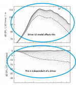
It’s a good reason to include a decent model of the driver in a BEM sim for something that is going to be built. The perfect planar source is handy to separate the horn contribution from that of the driver, but the response predicted is a little too good compared to what happens in reality.
It’s a good reason to include a decent model of the driver in a BEM sim for something that is going to be built. The perfect planar source is handy to separate the horn contribution from that of the driver, but the response predicted is a little too good compared to what happens in reality.
It's important to stress that the normalized SPL data, as calculated for a 'constant something' source (i.e. without a driver model), will stay exactly the same, no matter what driver model is used. What changes is the absolute SPL level as a function of frequency - that's the only change a particular driver model can cause.
(Of course this is only true as long as we consider an idealized wavefront at the throat, but the LE model doesn't change this in any way either.)
(Of course this is only true as long as we consider an idealized wavefront at the throat, but the LE model doesn't change this in any way either.)
Attachments
Last edited:
Is it already possible to generate an output for the Ripple Tank in Ath 4.7.2?My software only generates the input data for all these tools, by itself it doesn't simulate anything. So if there's a simulation, it's either ABEC (BEM) or the Ripple Tank applet (all of it is free, BTW).
Yeah, what is the ripple tank format 😀
I can't seem to see the pattern in their definition..
Btw Mabat,
When you did the meandering script..
Did you offset the (x) coordinate on on every meander with a fraction derived from the average path length?
I was considering taking the area of every meander and using that to calculate the offset instead of using the average path length. (maybe it's the same)
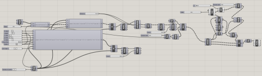
I'm still trying to make a script that does it parametrically in GrassHopper, so I can adjust stuff in real time with some sliders.
It looks something like this:


I can't seem to see the pattern in their definition..
Btw Mabat,
When you did the meandering script..
Did you offset the (x) coordinate on on every meander with a fraction derived from the average path length?
I was considering taking the area of every meander and using that to calculate the offset instead of using the average path length. (maybe it's the same)
I'm still trying to make a script that does it parametrically in GrassHopper, so I can adjust stuff in real time with some sliders.
It looks something like this:
Attachments

There are several things to consider, as I see it:
- First you have to decide on a target wavefront for the waveguide input. This can be either spherical (easier, IMO) with a conical waveguide or ellipsoidal for an OS waveguide.
- Outlets of the channels should be placed to form this wavefront shape and all the channels should have the same average length.
- The ratio of the input ring areas should match the ratio of the outlet areas (normal to velocity - on a spherical cap for the spherical wave), and the acoustic load presented on each channel should result in the same volume velocities at the outputs.
It's really not entirely straightforward but I still believe it can be done, maybe with a little help from some carefully prepared partial simulations.
- I will take a look at the ripple tank output, I forgot that (just beware it seems to have quite serious limitations).
Last edited:
If the phase plug manages to produce a spherical wave, then it would be perfectly fine to use a properly terminated conical waveguide, wouldn't it?
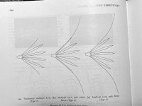
I'm a bit inspired by the discussion in Kolbrek and Dunker's book about upgrading the traditional multcell design.
I think incorporating a phase plug is doing kind of this.

I'm a bit inspired by the discussion in Kolbrek and Dunker's book about upgrading the traditional multcell design.
I think incorporating a phase plug is doing kind of this.
Attachments
Not only "fine", it would be the perfect fit for the conical waveguide, i.e. with no further HOMs generated. Better than a flat wave with an OS waveguide - that's the point. But as always, it's far easier to make a sketch than to make it actually work.If the phase plug manages to produce a spherical wave, then it would be perfectly fine to use a properly terminated conical waveguide, wouldn't it?
Last edited:
That is the reason why I'm trying to make a parametric sketch, that satisfies the conditions 😀
Hi Mabat,
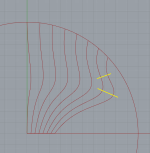
I'm not sure if I'm way off, but this geometry almost satisfies the conditions:
Throat size 50mm, sphere diameter is 200mm
It starts off flat and ends up spherical (with center the center of the throat)
Not sure if the outlets will form the waveform shape, but that's what ripple tank / Akabak will show.
All Chanels have nearly the same length.
The spherical caps (rings) have also nearly the same ratio of input vs output.
Acoustic load at each entrance and velocity at each output is not simulated on.
Could you be kind enough to share the ripple tank format?


Here is a .dxf of the drawing
View attachment onion.dxf.zip
I'm not sure if I'm way off, but this geometry almost satisfies the conditions:
Throat size 50mm, sphere diameter is 200mm
It starts off flat and ends up spherical (with center the center of the throat)
Not sure if the outlets will form the waveform shape, but that's what ripple tank / Akabak will show.
All Chanels have nearly the same length.
The spherical caps (rings) have also nearly the same ratio of input vs output.
Acoustic load at each entrance and velocity at each output is not simulated on.
Could you be kind enough to share the ripple tank format?
Here is a .dxf of the drawing
View attachment onion.dxf.zip
Last edited:
Without any closer examination of the rest, I think you should avoid such channel narrowing at all costs -

What you want is a channel that is continuously expanding. Also the velocity vectors at the outlets should be normal to the desired wavefront if possible, IMO. The question is how to determine the velocity vectors - I would assume that this is given by the direction of the channel "middle line" (if the channel is narrow enough). Also, I think there's no need for "meandering" of the center channel.
I'll need to look at the ripple tank format once again. Hold on.
Attachments
Last edited:
- Home
- Loudspeakers
- Multi-Way
- Acoustic Horn Design – The Easy Way (Ath4)