It might be interesting to experiment also with the delays of the radiating elements (see "Driving_Values" in observation.txt). I would guess that the apex of the dome is actually delayed compared to the voice coil. This might be frequency dependent but maybe some fixed value would be still better than nothing, I don't know, haven't tried.
For this it would be necessary to split the dome into several sections in the definition script, the same way as for the surround.
For this it would be necessary to split the dome into several sections in the definition script, the same way as for the surround.
Hey Mabat.
Been playing around with the 4.6. Couple of things:
1) You don't happen to have a link for superformula plot in Desmos?
2) Is there a limit how close the guide curve can be in the horn? I'm trying to set it around 20-30mm from the throat and slightly smaller diameter than the throat is but it's not able to create the mesh anymore. Happens with superellipse and superformula.
There is couple of typos in the manual. GGurve.type should probably be GCurve.type?
Also, you speak at that point about Coverage.definition parameter where as everywhere else it's been Geometry.definition. I presume these are the same thing as I can't find any other mention of Coverage.definition than this point, and even there it explains it like Geometry.definition.
It might be interesting to experiment also with the delays of the radiating elements (see "Driving_Values" in observation.txt). I would guess that the apex of the dome is actually delayed compared to the voice coil. This might be frequency dependent but maybe some fixed value would be still better than nothing, I don't know, haven't tried.
Fine tuning the diaphragm model was first on my list if I could use your tool to recreate the waveguides I have. I have a lot of data with all the tweeters and waveguides I have on hand and have measured that I'm confident I could find the best fit values, after that I can share the values and the community would have a pool of popular tweeters they could model easily in ABEC (SB26 family, T25B, RST28, SB21, SB29, DA25). And of course I can then move away from all this (very slow) iterative testing and be confident that if a certain design looks best in ABEC, it will be best in the real world too.
Last edited:
In light of augerpro's suggestion, it may be useful to start another thread, or allocate some space on the website to an overview (database) of "best practices".
This may include simulation and measurement data of (popular) compression drivers and dome tweeters with ATH4s would provide newcomers a tangible and practical basis, a handhold.
This may include simulation and measurement data of (popular) compression drivers and dome tweeters with ATH4s would provide newcomers a tangible and practical basis, a handhold.
In light of augerpro's suggestion, it may be useful to start another thread, or allocate some space on the website to an overview (database) of "best practices".
This may include simulation and measurement data of (popular) compression drivers and dome tweeters with ATH4s would provide newcomers a tangible and practical basis, a handhold.
At the moment I can't recreate my waveguides in ATH, unless mabat could add direct editing of the wall profile radius.
Update 4.6.1 released - see chapter 1.3 for details.
Thanks for pointing out the mistakes in the User Guide, should be correct now.
For a link to superformula plot in Desmos see the footnote in 7.4.2.
Thanks for pointing out the mistakes in the User Guide, should be correct now.
For a link to superformula plot in Desmos see the footnote in 7.4.2.
It is possible to define the exact radius now (see 7.6), I only don't see how will that help you if you don't know all the details of the original shape.At the moment I can't recreate my waveguides in ATH, unless mabat could add direct editing of the wall profile radius.
You would have to show me in more detail what you are trying to do. Generally, making it smaller than the throat will lead to a negative coverage angle which is maybe not what you are after. It may not be even possible to reach that target with the OS-SE formula. That's perhaps the reason it fails.2) Is there a limit how close the guide curve can be in the horn? I'm trying to set it around 20-30mm from the throat and slightly smaller diameter than the throat is but it's not able to create the mesh anymore. Happens with superellipse and superformula.
To show you what I mean -...It is possible to define the exact radius now (see 7.6), I only don't see how will that help you if you don't know all the details of the original shape.
First, you have the mouth outline given by an (exact) ellipse, that's how you need to do it, that's clear. Then you can define your horizontal and vertical radii quite simply but there still remain the unknown radii all the way between:
In your example the radii were 73.66 and 30.48 mm, which could translate to a formula like this one:
CircArc.Radius = 73.66 - (73.66 - 30.48)*sin(p)^u
The problem is that there's an endless continuum how to vary the radius in between - this can be adjusted e.g. by the exponent 'u' (u = 2,4,6,...). You may be lucky and get the exact match for some value of 'u'. Or maybe not - there's infinite number of such possible formulas. It shouldn't be a problem to get very close, however.
Last edited:
How would I find out what F360 is doing? I don't think using the measure function will do it but I'll try. Whatever the possibility, shouldn't there be one analytical solution that just makes sense? The smoothest change between to radius endpoints? I'll play with Desmos and see what the complication is. Thanks for the help so far mabat!
I would just open both the STL files (from ATH and Fusion) in MeshMixer, one over the other, and saw what's necessary to adjust.
EDIT: So horizontal radius is always the first term and vertical the second?
Geometry.Definition = 2
Throat.Profile = 3
CircArc.Radius = 73.66 - (73.66 - 30.48)*sin(p)^2
Throat.Diameter = 30.1 ; [mm]
Length = 19 ; [mm]
GCurve.Dist = 1.0
GCurve.Type = 1
GCurve.SE.n = 2.0
GCurve.Width = 127
GCurve.AspectRatio = 0.618
Geometry.Definition = 2
Throat.Profile = 3
CircArc.Radius = 73.66 - (73.66 - 30.48)*sin(p)^2
Throat.Diameter = 30.1 ; [mm]
Length = 19 ; [mm]
GCurve.Dist = 1.0
GCurve.Type = 1
GCurve.SE.n = 2.0
GCurve.Width = 127
GCurve.AspectRatio = 0.618
Last edited:
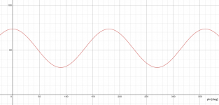
Yes, r = r_horiz - (r_horiz - r_vert)*sin(p)^2.
This way it is r_horiz horizontally and r_vert vertically with a smooth transition between the two.
This is how the whole function looks like, i.e. the radius around the waveguide -
This way it is r_horiz horizontally and r_vert vertically with a smooth transition between the two.
This is how the whole function looks like, i.e. the radius around the waveguide -
Attachments
Last edited:

It appears F360 uses u=2. Going to verify the *exact* measurements from my model again because even a .001mm or so makes a difference on how the meshes visually overlay each other in F360. As it is right now they are near perfect at u=2. I tried 2.32 which produced a closed form in Desmos, but ath couldn't solve, something about SVD not converging. I tried 4 and that was clearly the wrong direction. In fact less than 2 seems to be the answer, but I assume 2 is the minimum for usable solution, so the difference I see is probably due to tiny differences when rounding the dimensions from inches to millimeters.
Last edited:
Even with an "exact" match you will most probably see tiny differences due to the different surface "sampling" - the triangles of the STLs will be from different points in general. Errors on the order of 1/100 mm shouldn't bother you, IMHO. I wouldn't be bothered by 1/10 mm.
It's strange that the other (sensible) values don't work, I'll look at that.
It's strange that the other (sensible) values don't work, I'll look at that.
Last edited:
Yep, just tiny differences in rounding and creating the form in F360 vs ATH, where I see the walls diverge just a bit then reconnect. There is a value in the Loft command in F360 that is causing this I think. Anyway I'm quite certain now F360 is using u=2 or some equivalent in their equation.
Just to confirm: 2 is the smallest value we can use?
EDIT: it might be lower than 2. Desmos gives a usable solution at 1.92 but ATH is choking on it right now.
EDIT: it might be lower than 2. Desmos gives a usable solution at 1.92 but ATH is choking on it right now.
Last edited:
- Home
- Loudspeakers
- Multi-Way
- Acoustic Horn Design – The Easy Way (Ath4)