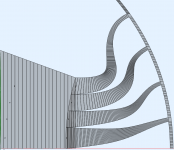
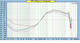
After all it seems to me that making the exit of the phase plug as small as possible is still the best solution for an even response. Also, the smaller it is, the less important the actual curvature of the wavefront will be as it more effectively averages out. At least these are my impressions so far. The principle I have presented may look interesting on paper at first but it seems to be only magnifying the problems in the end. This modal behaviour can be quite nasty and the remedy overwhelmingly complex.
Mabat,
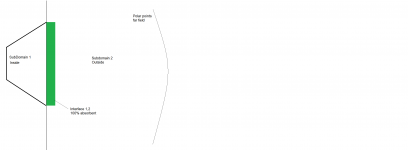
to obtain a far field polar and stil have a perfect temination, ABEC lets you add absorbtion to interface layer.
So you could couple your straight horn to the interfacer layer interfacing between the horn an the outside world and than make the interface layer completely absorbent.
This way you can exclude all the mouth reflections (basically having the perfect mouth roundover) and 100% focus on the effect of the phase plug.
keep up the good work!
Cheers,
Kees
That is exactly what I do now. To reduce the calculation time I just made the waveguide as short as possible (without too much affecting the throat itself). I can easily make the conical part longer to be more "far field" but now I'm not sure that was the request.
Another tip which I have used before;
-let ABEC generate a line reponse over the surface of the diaphragm with a very high angular resolution (0.001degree).
-Then run the sim with the channels not attached tot the compression chamber.
-now, if you open this reponse in a VACS contour plot, you can scroll through the angles and determine the optimum place for the channel entries, this is the location where the frequency response has no dips/peaks.
-then thank me later 😉
Won't be the pressure distribution across the chamber different after attaching the channels?-now, if you open this reponse in a VACS contour plot, you can scroll through the angles and determine the optimum place for the channel entries, this is the location where the frequency response has no dips/peaks.
That is exactly what I do now. To reduce the calculation time I just made the waveguide as short as possible (without too much affecting the throat itself). I can easily make the conical part longer to be more "far field" but now I'm not sure that was the request.
What I meant is that this way you could generate far field spectrum polars, which are much more insightfull than the field pictures.
Won't be the pressure distribution across the chamber different after attaching the channels?
No, not (almost not) if you place them perfectly following this rule.
but you have to sim in very high angular resolution and with high frequency resolution (sim with linear frequency distribution and at least 24points/ octave)
What I meant is that this way you could generate far field spectrum polars, which are much more insightfull than the field pictures.
Sure, to put some pressure probes inside the waveguide, somewhere near the terminating (absorbing) cap. But it would still be limited to the interior of the waveguide which is still not very realistic. But I will do that for sure as this polar map will carry a lot of useful information in one image.
Will try that! 🙂No, not (almost not) if you place them perfectly following this rule.
but you have to sim in very high angular resolution and with high frequency resolution (sim with linear frequency distribution and at least 24points/ octave)
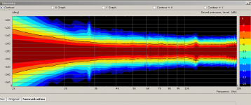
I have created a custom 40 degree phaseplug fot an excisting 4inch compression driver for a customer in the past following these rulses.
If you do this well, you van just go directly to conical from here on and if works well.
The attached directivity plot is a sim with the horn in freefield conditions, so no infinite baffle.
The 3D printed protoype performed nearly identical to the sims, but the cutomer found the phase plug too expensive to produce, since its feutures a 4 channel slit which needs very low tolerance CNC-ing.
I am sorry that I can't share more details, since the customer paid me to do this for them.
Kees
Attachments
Last edited:
Sure, to put some pressure probes inside the waveguide, somewhere near the terminating (absorbing) cap. But it would still be limited to the interior of the waveguide which is still not very realistic. But I will do that for sure as this polar map will carry a lot of useful information in one image.
Sorry I am not explaining myself properly;
use the interface layer to couple to an outside domain (via the infinite baflle) and make the interface 100% absorbent, now you can make a far field directivity plot with point laying in the outside domain at i.e. 50m distance
Are you saying that there will still be a wave propagation behind the 100% absorbent interface to the outside domain? That would not be my guess, I must admit. Thanks for the picture.
- To your phase plug work, all I can say is just - wow!
It will be very good to have you around 🙂 Please stay.
- To your phase plug work, all I can say is just - wow!
It will be very good to have you around 🙂 Please stay.
Are you saying that there will still be a wave propagation behind the 100% absorbent interface to the outside domain? That would not be my guess, I must admit. Thanks for the picture.
- To your phase plug work, all I can say is just - wow!
It will be very good to have you around 🙂 Please stay.
Yes that is correct.
no worrries, I'll stay connected! It is very nice to see the work that's being done by you, as you can see in my post I have always done everything in excel sheets, since I like to look at the number ranges, a bit of a tick of mine 🙂
and regarding my design work, thank you! I am just standing on the shoulders of giants, hats off to people like Earl Geddes and Jack Ocklee-Brown!
Last edited:
One final tip (probably the most important one, costed me days to figure out);
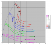
as you can see in my excel channel overview I keep all channels equal length. this is mandatory to get equal loading on all channels, if you fail to do so you get all kinds of extra resonances.
So I create the needed time delay for the wavefront curvature by physically placing the excits of the channels.
This is something I've been wondering about a lot. I wanted to calculate the acoustical impedances of the individual slots and make sure they are the same, not only by manipulating the lengths but also the areas and angles (may be too ambitious or even wrong). Now I have the tools so it's time to really concentrate on the optimization part. If you needed days, I would be much slower than you.
Thanks for your input! Much appreciated indeed.
Thanks for your input! Much appreciated indeed.
Last edited:
Kees, looking at the channels of your phase plug, it seems that you've created a "stepped plane wave" at the exit. So is it really good enough to be connected directly to a conical horn, as you suggest? If that was the case then a concave side of the diaphragm could be used. For a long time I considered this to be impossible. Yet you seem to have succeeded.
Yeah I think it is possible (as I have seem to have done it 😉 ) the stepped thing is relative to the wavelengths involved but has a bit tolerance as you will see.
My advide; take it step by step;
1-define where the input of the channels will be located by the steps I described before
2- define where your outputs need to be phyusically located to ge the desired wavefront
3-define the compression ratio you want to achieve (this will affect loading but also nonlinear distortion which can not be modelled by ABEC, I suggest lowish for hifi, like 1:7 for instance)
4-model the channels connected to the compression chamber but UNCONNECTED to a horn but all terminated by perfect absorbtion at the end, put measuring points right at the end of each channel and match the amplitude within +-1dB and the phase within +-10deg .
This is the hard part, play with curvatures en shapes as much as needed to achieve the goals
5-attach horn and verify goals
6-3Dprint
7-build speaker
8-have a nice drink and enjoy incredible sound 😉
Yeah I think it is possible (as I have seem to have done it 😉 ) the stepped thing is relative to the wavelengths involved but has a bit tolerance as you will see.
My advide; take it step by step;
1-define where the input of the channels will be located by the steps I described before
2- define where your outputs need to be phyusically located to ge the desired wavefront
3-define the compression ratio you want to achieve (this will affect loading but also nonlinear distortion which can not be modelled by ABEC, I suggest lowish for hifi, like 1:7 for instance)
4-model the channels connected to the compression chamber but UNCONNECTED to a horn but all terminated by perfect absorbtion at the end, put measuring points right at the end of each channel and match the amplitude within +-1dB and the phase within +-10deg .
This is the hard part, play with curvatures en shapes as much as needed to achieve the goals
5-attach horn and verify goals
6-3Dprint
7-build speaker
8-have a nice drink and enjoy incredible sound 😉
Hmm.
This seems to indicate that the exit angle of the phase plug should be matched to the input angle of the waveguide.
Also seems to imply that ideally, we want little to no divergence between these two angles.
(I know Geddes has a patent on phase plugs that do this.)

For instance, here's the polars of QSC's QSC PL-000446-GP waveguide, with the Eminence N151M. I've been raving about this combo for months; costs less than $100 and I'm not aware of anything that can beat it for under $100.
In the attached image, we see the response of the B&C DE250 on the same waveguide. The B&C is good but the Eminence is better. The Eminence is cheaper, it's more extended, it's smoother.
If I'm understanding your post correctly, I have a hunch that the superiority of the Eminence may be due to the larger exit angle? It has an unusually large exit angle - about 35 degrees.
Taking this a step further, one might argue that the oblate spheroidal geometry is a bit of a "band aid" on this problem: it minimizes the effect of the transition from a narrow throat angle to a wide horn angle. But perhaps the ideal solution is to fix the phase plug, so that we don't need that transition from throat to waveguide at all.
IE, if I want a coverage angle of 90 degrees, perhaps I need a phase plug that produces a wavefront of 90 degrees?
Attachments
- Home
- Loudspeakers
- Multi-Way
- Acoustic Horn Design – The Easy Way (Ath4)
