Hi Marcel,
Thank you,
M
Why not - I don't plan to sell it (as you don't, I hope).
Thank you,
M
Did you ever consider to push the woofer closer to the horn axis, just let it take a small "bite" out of the mouth?
The relationship between the distance between the axes and the bite area is non linear- the bite area increases approximately quadratically as the axis separation falls linearly so obviously can't be pushed too far.
But it seems a small bite would have minimal impact on the horn polar yet improve the vertical combined polar.
Once you approach a crossover at 500 Hz (wavelength = 27.12"), C-C spacing becomes less of a problem.
Additionally, I don't think it would hurt to let a free-standing waveguide hang over the top woofer edge, like this:
Attachments
Last edited:
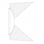
Just thinking aloud, couldn't this work reasonably well?
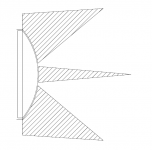
A compression driver on the left (open back side), conical waveguide on the right. An OS throat could be used instead to better match the actual curvature of the diaphragm.
Ro808: From the photo I would think there will be much more serious problems than the driver spacing in that case.
A compression driver on the left (open back side), conical waveguide on the right. An OS throat could be used instead to better match the actual curvature of the diaphragm.
Ro808: From the photo I would think there will be much more serious problems than the driver spacing in that case.
Attachments
Last edited:
Isn't it easier to prevent the holes...
Certainly doable, but maybe not "easier" depending on your resources. For me it was not that easy since I did most of my molds on a lathe. As I said, CNC was very expensive...
Seems you two have somewhat different ideas in mind.
Marcel did you mean to keep it axisymmetric but add an extended transition curve?
Earl, what did you have in mind?
Once you approach a crossover at 500 Hz...less of a problem
I don't see why, as the crossover frequency decreases the size of the horn increases and so does the C-C.
It all just scales, same problem.
Ok, maybe the woofer size doesn't increase, helps a little but not much.
Additionally, I don't think it would hurt to let...like this:
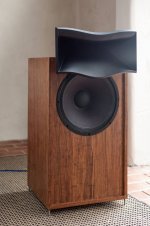
Looks like a Dali horn, not the Danish company but Salvador😉
The style you show looks sub optimal to me.
I have always expected there would be interference and reflections.
But I must admit I have never seen it actually measured, anyone have any data?
I planned to blend the horn into the front baffle, not so dissimilar to Earl's Summa.
Or many others with excellent measured performance, Genelec and so on.
Best wishes
David
Last edited:
Hmm, the C-C problemo between a woofer and a horn would be solved by a big horn that goes down to Schroeder frequency?🙂 Multiple entry horn then.
ps. s and n parameters would tune the length of straight section of the horn profile? maybe find longest straight section that yields good performance and fits some midrange drivers 🙂 mabat posts #1454 >.
pps. thanks mabat for the ABEC project #1378! will try
ps. s and n parameters would tune the length of straight section of the horn profile? maybe find longest straight section that yields good performance and fits some midrange drivers 🙂 mabat posts #1454 >.
pps. thanks mabat for the ABEC project #1378! will try
Last edited:
Plainly, it seems to me that it should be possible to make an 18" axisymmetric waveguide (as in NS15) without the axial hole(s). I even think I have already shown that. I considered that settled.Seems you two have somewhat different ideas in mind.
Marcel did you mean to keep it axisymmetric but add an extended transition curve?
In fact, it it possible for any waveguide size without a significant harm to the pattern control - if not improving it actually. But you won't achieve that by adding a simple radius to the end of the waveguide. At least I think this is clear from the analysis made so far. There simply don't have to be any axial holes (i.e. mouth reflections) in any waveguide.
Last edited:
I believe this doesn't have to be the case. Considering how smooth the DI decrease for a good waveguide can be with decreasing frequency, there is no need to increase the waveguide size, IMO. The overall DI decrease towards lower frequencies, which would be otherwise contributed to the woofer, can be as well (or even better) handled by the waveguide. Then you can use even a smaller woofer and cross it lower. It "only" requires a CD that can handle a lower crossover point (which would lead to a 1.4" as there are some pretty good pieces these days)....I don't see why, as the crossover frequency decreases the size of the horn increases and so does the C-C.
It all just scales, same problem. ...
Plainly, it seems to me that it should be possible to make an 18" axisymmetric waveguide (as in NS15) without the axial hole(s). I even think I have already shown that. I considered that settled.
In fact, it it possible for any waveguide size without a significant harm to the pattern control - if not improving it actually. But you won't achieve that by adding a simple radius to the end of the waveguide. At least I think this is clear from the analysis made so far. There simply don't have to be any axial holes (i.e. mouth reflections) in any waveguide.
I would disagree here because it is possible to make the axial hole go away with a mouth radius only. The hole results from diffraction of the mouth and as the mouth radius is increased this diffraction will decrease and the hole becomes negligible. The NS-15 does not actually have an axial hole, nothing pronounce at any rate - its mouth radius is much larger than the Abbey, which has a much more pronounced axial hole.
In a small device it is not possible to do a large radius so smaller devices tend towards an axial hole if they are axisymmetric.
Then you can use even a smaller woofer and cross it lower. It "only" requires a CD that can handle a lower crossover point (which would lead to a 1.4" as there are some pretty good pieces these days).
If you use a smaller woofer and a lower crossover point won't that make the polar responses differ at the crossover?
Last edited:
May as well live inside a waveguide then!Hmm, the C-C problemo between a woofer and a horn would be solved by a big horn that goes down to Schroeder frequency?🙂 Multiple entry horn then.
ps. s and n parameters would tune the length of straight section of the horn profile? maybe find longest straight section that yields good performance and fits some midrange drivers 🙂 mabat posts #1454 >.
pps. thanks mabat for the ABEC project #1378! will try
That is certainly true. My point was that if you have a waveguide still showing something like an resemblance of an axial hole, it could be most probably improved without increasing the overall size just by replacing the radius by a more gradual flare. And that this would also lead to even more consistent polar response.The hole results from diffraction of the mouth and as the mouth radius is increased this diffraction will decrease and the hole becomes negligible.
Maybe it's not such a problem but it's still about 5 dB on axis. Could still be improved to negligibility, IMO.The NS-15 does not actually have an axial hole, nothing pronounce at any rate - its mouth radius is much larger than the Abbey, which has a much more pronounced axial hole.
They may be slightly different (both being already quite a low DI value) but they will blend seamlessly in the summation. At least this is my experience. Also it will be already in a frequency range where it should matter less and less as you go lower and lower with the crossover point.If you use a smaller woofer and a lower crossover point won't that make the polar responses differ at the crossover?
At least this is my current understanding of these issues at the moment.
Last edited:
I don't agree with the 5 dB hole, but that is beside the point. A more gradual flare may help, the sims seem to show that, but I have not seen this born out in actual measurements of a real device, so it's hypothetical at this point.
And I just don't follow your discussion of woofer to waveguides. You'd have to explain better or show some examples, because this just does not jibe with my experience. The DI rises with frequency for the woofer and should be constant for the waveguide unless it is too small, in which case its DI become erratic - not smooth or constant - and matching it with the woofer is problematic as will be the final result. It will not "blend seamlessly" in my estimation.
And I just don't follow your discussion of woofer to waveguides. You'd have to explain better or show some examples, because this just does not jibe with my experience. The DI rises with frequency for the woofer and should be constant for the waveguide unless it is too small, in which case its DI become erratic - not smooth or constant - and matching it with the woofer is problematic as will be the final result. It will not "blend seamlessly" in my estimation.
Well this is your own data. I wouldn't make that up 🙂I don't agree with the 5 dB hole, but that is beside the point.
Attachments
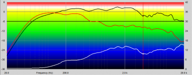
The hole should be measured against the falling response not against the peak. It's how you interpret the data that matters.
Fair enough. I see a typical axial hole that I also see in the sims when the mouth termination is too abrupt and that goes away when the mouth flare is more gradual. That's all I can say...
Last edited:
OK. In the end, the whole loudspeaker won't have a constant DI, that's for sure. It will rise and then (say) stays constant. Thus there is no reason why one should be using the waveguide only in the range where it has a constant DI since a good waveguide won't have an erratic DI below this range - it will fall gradually. So, some portion of the raising DI part can be left to the waveguide. That lowers crossover point and also the DI values at this frequency. And from my experience (don't have the plots at hand), this is then a lot less critical than say at 1 kHz. Partly due to the better C-C.And I just don't follow your discussion of woofer to waveguides. You'd have to explain better or show some examples, because this just does not jibe with my experience. The DI rises with frequency for the woofer and should be constant for the waveguide unless it is too small, in which case its DI become erratic - not smooth or constant - and matching it with the woofer is problematic as will be the final result. It will not "blend seamlessly" in my estimation.
That's basically a regular compression driver without a phase plug, no?Just thinking aloud, couldn't this work reasonably well?
A compression driver on the left (open back side), conical waveguide on the right. An OS throat could be used instead to better match the actual curvature of the diaphragm.
Ro808: From the photo I would think there will be much more serious problems than the driver spacing in that case.
As for this experiment with the convex side of the diaphragm, my whole reasoning was that it must be easier to get a spherical wavefront from that side than from the concave one (via phase plug and OS throat). I think I will at least give it a try in the simulator to see what I can get. Just in case someone wrote that it's completely silly and why, I would save some effort.
Last edited:
- Home
- Loudspeakers
- Multi-Way
- Acoustic Horn Design – The Easy Way (Ath4)