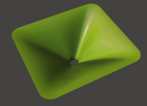
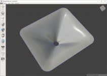
The chamber reduced to a minimum, with horn entrance only 1 mm from the source. It may be hard to see from that.What's that?
"Protruding" the walls inward really seems to help. Not quite there yet - some form of knuckles will be needed I guess 🙂 The diagonals start to suffer however.
(Still the same 33 mm throat.)
- This horn I would be satisfied with.
(Still the same 33 mm throat.)
- This horn I would be satisfied with.
Attachments


Last edited:
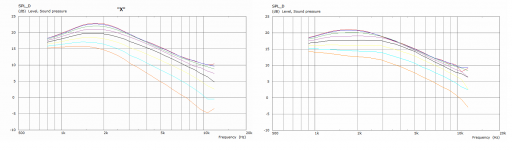
Now let me show you something:
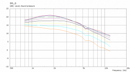
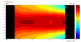
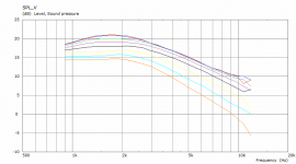
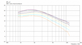
- the plots below are for horizontal, vertical and diagonal polars (a 7.5 deg@2m)
- on the left is the M2 clone (shown before) labeled "X", on the right an OS waveguide made squarish, aka "ATH"
- these two have the same throats (33 mm) and are about the same size
ATH has nothing you would call a diffraction slot, I assume. I just can't see where is this M2 clone actually better, having one. I see a tighter pattern control with the ATH overall, it is virtually as good diagonally as horizontally or vertically. What I am missing? I'm sorry but this "optimized diffraction slot" thing seems like a fairy tale to me. At least for a pattern control. I can't comment on HOMs.
Fundamentally, the way that horns and waveguides work is that they take the same amount of energy and they focus that energy into a narrower beam.
A round oblate spheroidal waveguide will 'illuminate' the room consistently. IE, the sound on the vertical axis is identical to the horizontal axis and is identical to the diagonal axis.
The JBL "high definition imaging" waveguides have a diffraction slot that's shaped like an "X."
The diffraction slot does three things:
1) it narrows the directivity on the diagonal axis
2) it widens the directivity of the horizontal and the vertical axis. I like to describe this as "robbing Peter to pay Paul." Basically the HDI waveguides improve the response on one axis by degrading the response on another.
3) When sound radiates into a narrower beam, the output goes UP. Because the volume of an HDI waveguide is smaller than an oblate spheroidal waveguide, the HDI waveguides are more efficient.
These three things are illustrated in your simulations. Note that the HDI waveguide has similar beamwidth to the oblate spheroidal waveguide, but the HDI waveguide is 3dB more efficient at 2khz.
It doesn't, just look at the data. The same beamwidths can be achieved without it so how can you say that it widens the directivity?...
2) it widens the directivity of the horizontal and the vertical axis.
It doesn't, just look at the data. The same beamwidths can be achieved without it so how can you say that it widens the directivity?
That's a good point:
A big part of the reason that I'm fascinated by the HDI waveguides is because I've found that wide beamwidth waveguides don't behave as simulated in the real world.
For instance, I've 3D printed waveguides that were 33cm wide, which performed no better than a 16.5cm waveguide.
From simulations that I've done in ABEC, I believe that what's happening is that the wavefront radiated by the compression driver can't expand fast enough. Due to this, the waveguide behaves as if the walls of the waveguide aren't there.
My 'hunch' is that this is happening because some waveguides produce a converging wavefront, some produce a diverging wavefront, and some produce a flat wavefront.
The JBL HDI waveguides sidestep a lot of this, because the walls are 'pinched.'
In addition to this, there's a couple other reasons to use the HDI waveguides:
1) they look cool
2) they produce higher SPL than an O.S. waveguide
I'm not saying they're the greatest thing on earth, just saying that I'm a fan. If you prefer oblate spheroidal, that's perfectly reasonable, OS performs really well.
I'm not a fan of any particular shape, I only can't stand beaming sources, so of those I'm really not a fan. I look at the data and when it contradicts the claims I would like to get straight what's going on, possibly to understand it better. The last explanation I would accept is that there is some mysterious phenomenon that's hard to grasp. 🙂
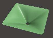
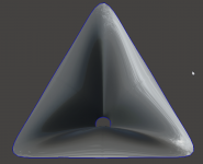
Hey, this looks fine (374 x 336 mm) -
ThroatDiameter = 33 ; [mm]
ThroatAngle = 0 ; [deg]
Coverage_Horizontal = 110; [deg]
Depth = 120 ; [mm]
SE_s = 0.7
SE_n = 4.0
SE_q = 0.995
Depth.ConicSectionPart = 1.0
Shape = raw2rect
Shape.FixedPart = 0.01
Shape.CornerRadius = 40 ; [mm]
Shape.StretchExp = 3
ShapeCurve = SF
SF = 1.65,2.3,4,2,5.1,2.9
SF.Rot = 0
; Mesh Setting
Mesh.AngularSegments = 100
Mesh.DepthSegments = 28
Mesh.CornerSegments = 10
...
Attachments
Last edited:
Meshmixer. With a few clicks, hard to beat.
Much improved! Thank you.
Attachments
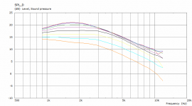
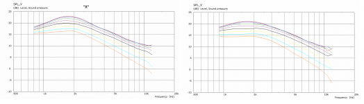
So this is the updated comparison - the second take on the "ATH" (on the right). This one looks like a "nude" version of the M2 clone.
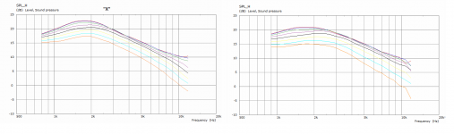
OK, the knuckles add this bump in efficiency (?) around 1,7 kHz. Is that all?
OK, the knuckles add this bump in efficiency (?) around 1,7 kHz. Is that all?
Attachments
Last edited:
Seems the over 10K response is smoother without the big dip in the M2 clone, could you extend the sim to go to 20K to see it better? This might well be one of those things that turns out to be different in reality unless you model the exact exit of the driver to horn interface, but interesting as augerpro was putting a lot of effort into minimizing that issue with his shallow waveguides and sim to reality was quite close.OK, the knuckles add this bump in efficiency (?) around 1,7 kHz. Is that all?
With a 33mm throat the compression driver determines the polar pattern above 10KHz, not the waveguide. I would argue the plots are going too high already.
So why does the simulation change between waveguides when it's being driven by an ideal device?
With a 33mm throat the compression driver determines the polar pattern above 10KHz, not the waveguide. I would argue the plots are going too high already.
Yep.
Ideally we should be doing the ABEC sims all the way down to the diaphragm. (including the phase plug in the sim.)
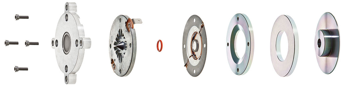
In the JBL 2409H the phase plug is barely there, just a few centimeters deep.
And in the 2410H, it appears to be sticking out of the waveguide itself! Seems to imply that the ring radiator diaphragm may be less than a centimeter from the waveguide.
Basically the phase plug is disappearing.
Attachments
With a 33mm throat the compression driver determines the polar pattern above 10KHz, not the waveguide.
This is not correct. A waveguide done properly can go well above what is considered the region where it is assumed that the driver dominates.
So why does the simulation change between waveguides when it's being driven by an ideal device?
Because of what I said above, it's incorrect. Some drivers with poorly coherent exit wavefronts may have more trouble than others, but there is no theoretical reason why the above should be true, nor was it true in system that I made.
Try measuring a bare compression driver, they show significant pattern control above 10KHz. How can a waveguide without a diffraction slot make this wider? I'm assuming your "waveguide done properly" does not have a diffraction slot.
Hey Marcel, congratulations on 1000 posts in this thread. It shows the value of the software you have put together here.  and thank you!
and thank you!- Home
- Loudspeakers
- Multi-Way
- Acoustic Horn Design – The Easy Way (Ath4)