What does the program print as a "Project path"? There should be the name of the script (without an extension) in this path. It seems like it gets corrupted/lost in your case but I can't understand how this could happen.It has created the directory D:\Horns\ABEC_project with four files in it.
If there are only four, probably the *.msh file is missing (which is quite a pity).
It seems like the program argument (the script name as a command line parameter) is not passed correctly.
Last edited:
IMPORTANT:
Please (to all), use the line Out.DestDir = "D:\Horns" in the scripts, only set it to some directory that exists in your environment.
Your output files should then get created under this directory in subdirectories corresponding to script names. This is the standard way how to proceed. Otherwise you may get a mess.
Last edited:
Fredrik, you can look for Gmsh configuration files on your computer and try to find something that may affect the mesh density (or just try to delete them). I just realized that during the initialization of the SDK (gmsh::initialize()), it reads these files by default:Tried it on my laptop now and the mesh is normal resolution there.
"If 'readConfigFiles' is set, read system Gmsh configuration files (gmshrc and gmsh-options)."
On my PC these files are in C:\Users\Me\AppData\Roaming.
That could be an explanation. I should probably disable this.
Last edited:
Thankyou. I'm getting closer, I'm now coming up with an error "Unknown output file format" when I try to open oswg.cfg. This error appears just after the width and height of the wg is displayed.
It has created the directory D:\Horns\ABEC_project with four files in it.
Here's a few things to keep in mind:
1) if you run the ath4.exe binary in Windows Explorer, it won't do anything, because it's a command line executable. So it must be run from a DOS window. ("cmd.exe") It might work in Power Shell too, I haven't tried.
2) ath4.exe depends on a configuration file to work. That configuration file is named "[your project name].cfg" For instance, the "ath15" example is named "ath15.cfg"
3) Windows may be configured to use "cfg" files with another application. Because of this, if you double click on the files in Windows Explorer, they may be opened in something else. So you'll want to open those "cfg" files in Windows Notepad, or whatever text editor you prefer. To do so, right click on the "cfg" files in Windows Explorer, and select "open with..." and then choose "Notepad."
If you configure the "cfg" files correctly, then you can run "ath4.exe [your config file].cfg" and ath4 will spit out an ABEC project and it's required files. You can tell if it worked correctly by opening the "project.abec" file in ABEC. If it worked, you will see a wireframe model uder the "Drawing" tab in ABEC.
Hope that helps!
I could make an option of a dome tweeter instead of a plane wave (which is what it is now) for the throat. At least I believe it would be possible. Only it is not so obvious how to do it. Should I include the surround? How to define the shape? Or does that make any sense at all?
BTW, the wavefront could also by modeled as non-flat. I only don't know if there is anyone who could utilize such feature.
Yes, this would be an awesome feature. One way you might implement it is to add a stanza to the cfg file for the following:
1) diameter of dome
2) diameter of surround
3) height of dome
You might want to set things up so that these parameters would override the "ThroatDiameter" parameter. In other words, if the user selected a 25mm dome with a 5mm surround, that would yield a throat of 35mm. So if the user selected a throat of 25mm or 50mm, that would cause issues with the model. (Because there's a mismatch.) So you might want to have the dome settings "override" the "ThroatDiameter" setting in the config file.
Actually you can rename your script files to any other extension you like, *.txt if you wish. It's really up to you. What is important that you edit them by a plain text editor - Notepad, notepad++ (which I strongly recommend), etc.
I'll try the dome. How much should the surround contribute to the total output? 🙂 Should it be gradually attenuated? The surrounds don't move along the edge... Does it matter? These are the questions.
I'll try the dome. How much should the surround contribute to the total output? 🙂 Should it be gradually attenuated? The surrounds don't move along the edge... Does it matter? These are the questions.
Last edited:
Mabat,
Huge thanks for this amazing package.
Just say I was interested in simulating 7-sided (or any other odd number) gramophone style horns is there a way of setting Mesh.AngularSegments to do this? At the moment 7 defaults to 8.
thanks!
Huge thanks for this amazing package.
Just say I was interested in simulating 7-sided (or any other odd number) gramophone style horns is there a way of setting Mesh.AngularSegments to do this? At the moment 7 defaults to 8.
thanks!
Right now the number of angular segments is rounded to the nearest multiple of four to be able to export the exact quarter of the horn for ABEC (employing symmetry). I can relax this limitation, then the whole horn will need to be meshed and calculated. But there's a catch. Done this way there will be only 7 segments from throat to mouth. Maybe a better solution would be to add a superformula as an option for the s-curve. I guess you could easily do that shape - Superformula - Wikipedia
Example 10 | Superformula Shape | Super-formula Plotter
Can be done.
Example 10 | Superformula Shape | Super-formula Plotter
Can be done.
Last edited:
In that regard, any curve >>could<< be used as the s-curve (see the Manual for explanation). I just haven't found a way of how to import the curve data. Could be DXF or something - I would need to learn that.
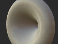
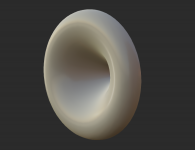
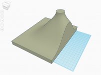
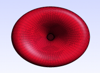
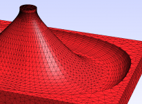
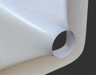
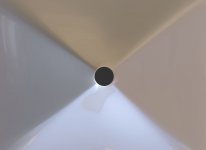
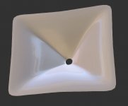
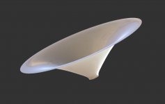
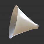
These are just some pictures from the coming functionality - a mold preparation. BTW, the STLs can be imported also to Tinkercad smoothly.
Now I would like to try to make horns myself from A1 acrylic resin: AcrylicOne
Does anybody here have any experience with this material? Maybe not so strong, but seems to be quite "user-friendly".
Now I would like to try to make horns myself from A1 acrylic resin: AcrylicOne
Does anybody here have any experience with this material? Maybe not so strong, but seems to be quite "user-friendly".
Attachments
-
 gmsh-wg8.png75.2 KB · Views: 1,210
 -
 gmsh-wg-108.jpg197.4 KB · Views: 404
 -
 gmsh-wg-107.png181.6 KB · Views: 397
 -
 TCAD_cut.jpg77.8 KB · Views: 382
 -
 TCAD.jpg124.4 KB · Views: 384
 -
 kopyto.png36.5 KB · Views: 1,177
 -
 gmsh-wg-fa5.png86.5 KB · Views: 1,193
 -
 gmsh-wg-fa4-p2.png160.2 KB · Views: 1,203
 -
 gmsh-wg-fa2.png150.8 KB · Views: 1,199

Ath4 script definition:
; -------------------------------------------------------
; Horn Geometry Definition
; -------------------------------------------------------
ThroatDiameter = 39.0 ; [mm]
ThroatAngle = 0 ; [deg]
Coverage_Horizontal = 90 ; [deg]
Coverage_Vertical = 80 ; [deg]
Depth = 200 ; [mm]
Depth.ConicSectionPart = 0.2
Shape = raw
SEExp = 8.0
Termination = baffle
Termination.Scale = 0.3
; -------------------------------------------------------
; Horn Geometry Definition
; -------------------------------------------------------
ThroatDiameter = 39.0 ; [mm]
ThroatAngle = 0 ; [deg]
Coverage_Horizontal = 90 ; [deg]
Coverage_Vertical = 80 ; [deg]
Depth = 200 ; [mm]
Depth.ConicSectionPart = 0.2
Shape = raw
SEExp = 8.0
Termination = baffle
Termination.Scale = 0.3
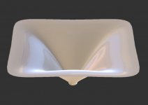
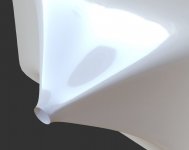
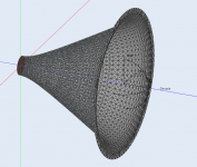
Throat detail -
(hyperbola+clothoid everywhere)
(hyperbola+clothoid everywhere)
Attachments

Last edited:
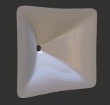
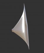
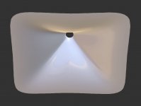
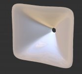
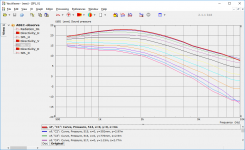
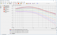
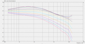
Making it shallower won't work as nice (this one is 506 x 416 x 140 mm; 110 x 100 deg nominal coverage).
Still usable, however.
Still usable, however.
Attachments
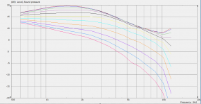
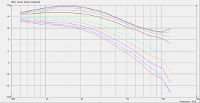

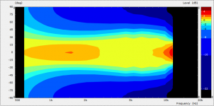

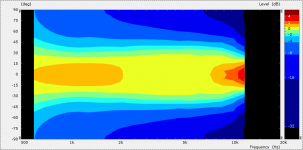

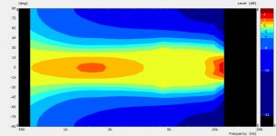
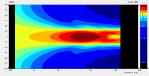

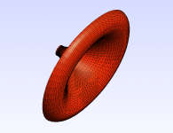
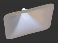
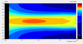
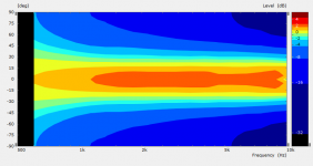
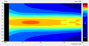
A bit more rounded mouth edge (still too small to have a noticable effect) and a bit more finer resolution.
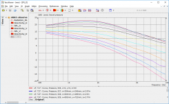
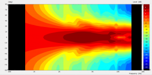
I almost like the log-shaded polar maps better.
I almost like the log-shaded polar maps better.
Attachments

- Home
- Loudspeakers
- Multi-Way
- Acoustic Horn Design – The Easy Way (Ath4)