I think it is absolutely necessary or the acoustical results will not be correct. But we all have different needs and wants 🙂
//
//
All that matters are the resulting acoustic responses, not the initial state. You don't have to start with flat responses - it does no harm but it's superfluous. It simply makes no difference.
Last edited:

The region from about 1.5 k to 4k is the area in which our hearing gives us spatial cues. Actually it starts a little lower, but the point for this graph is that you have a fairly large dip where it actually will be audible very readily.I didnt think it would work either but it actually sounds really good.
this is from REW with 1/6th smoothing after dirac (in room) . Yeah it is very far from flat but it sounds great tbh. I will put some more effort into it once the horns are smooth and painted and there is a pair of them.
I also time aligned each driver in the hypex amp and you can't tell sound is coming from the speakers it's just floating in space and sounds very real.
Green is your horn design mabat and purple is the PAP wood horn
View attachment 1426215
So how do you end up with ideal XO slopes - whats your way of doing it?All that matters are the resulting acoustic responses, not the initial state. You don't have to start with flat responses - it does no harm but it's superfluous. It simply makes no difference.
//
You can eq flat then add the crossover.
But for example, for a LR24 crossover target, you can add a capacitor so 6db at high FR like maybe 10k then add a butterworth of any type at any FR to match a LR24 and tweak the remaining with EQ. At the end the acoustical target is right but you have never used an electrical LR24.
Thomas
But for example, for a LR24 crossover target, you can add a capacitor so 6db at high FR like maybe 10k then add a butterworth of any type at any FR to match a LR24 and tweak the remaining with EQ. At the end the acoustical target is right but you have never used an electrical LR24.
Thomas
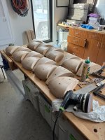
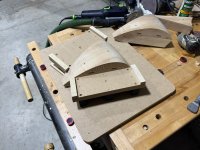
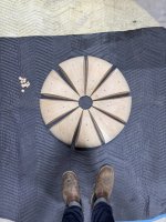
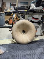
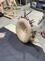
I thought I'd post a fabrication update since none of my friends are woodworkers and my wife (bless her soul) feigns interest but probably doesn't care much - I finally got all of the petals milled, glued, and pieced together. I cut in some domino mortise slots to help with alignment and did a down-and-dirty dry fit tonight to see how it would fit together as now - after all that work - was really the only moment I'd be able to see if it actually fits together or not. Thankfully, everything went together smoothly and there's maybe 1 miter with 1/64" of a gap I can probably fudge. I think I am going to route a 1/8" fillet at the edges of each of the petals to really emphasize the "petal" quality, but overall the toughest part of this project has come together pretty well.
Attachments
So the correct method is to measure and eq on a per driver basis? But I should be doing that gated or in a anoectic chamber?
I'm going to need another usb cable so i can have my amps plugged in at the same time as the mic
I'm going to need another usb cable so i can have my amps plugged in at the same time as the mic
That looks very cool and also a ton of work! reinforcing my choice to buy a 3d printer instead of a CNC machine 😀I thought I'd post a fabrication update since none of my friends are woodworkers and my wife (bless her soul) feigns interest but probably doesn't care much
Thanks for drawing my attention to that - Yeah I suspect you might be right and I'll look into it and see what is going on. A similar dip at the subwoofer area too.What if the below dip is there because the horn and the woofer(s) are cancelling each other, i.e. they are not well in phase?
What do you think can the Dirac do? It will only increase the voltage in that region. Instead of solving the issue it will only drive the transducers harder.
Then you come and say that the driver needs to be crossed higher... Well, when treated like this it probably does 🙂
yes: per driver, in enclosure, gated, with angles: -> vcad -> XO-sim -> speaker application -> re-measure -> (/circle)So the correct method is...
https://www.grimmaudio.com/wordpress/wp-content/uploads/speakers.pdf
https://www.audiosciencereview.com/...ents-spinoramas-with-rew-and-vituixcad.21860/
https://kimmosaunisto.net/Software/VituixCAD/VituixCAD_Measurement_REW.pdf
My favourite is epoxy filled with metal powder (brass, aluminum). It is quite laborous, kind of a craft, but the results can be really rewarding, especially if you don't mind (or even like) the idea that it looks a bit "worn-out". The idea is to hide as much print residuals as possible. Instead of metal powder you could also just color an epoxy with pigment. But I find epoxy in general really good for this, as it also hardens the whole thing significantly.
Or something like this: https://www.k2-global.com/en/products/k2-bumper-400-ml
Or something like this: https://www.k2-global.com/en/products/k2-bumper-400-ml
Last edited:
Electroplating the final part would be cool but what a tedious job.
A fairly easy way is acrylic paint, there are many colors available.

looks good, is the 520 horn and 18 inch?
Stunning! would love to know about the basic setup of that system.
looks good, is the 520 horn and 18 inch?
It's more like an update, past pages had past versions of the system, now closer to the finish than ever 🙂Stunning! would love to know about the basic setup of that system.
- RCF nd940 in 520 horn
- 18'' Faital Pro 18fh500 in resistive cardioid box (not finished, but generally works - there are resistive ports on the back wall, I still want to try to do the side wall as well)
- 2х10'' servo subwoofers on the wardrobe under the ceiling
- Hybrid crossover ~400 Hz, passive + overal EQ (not finished, but good enough))
- The subwoofers work together with the mains up to 100 Hz
- Lyngdorf TDAI-1120 - amp, EQ, bass management
- Home
- Loudspeakers
- Multi-Way
- Acoustic Horn Design – The Easy Way (Ath4)