Here is attempt to train intuition with waveguide depth and rotating axis by visualizing and making it interactive:
https://www.desmos.com/geometry/zmwyitoecg
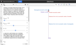
It's missing waveguide profile though, and how it would increase path length beyond ~nominal coverage angle, but this doesn't affect things in listening window so not the most important thing here, sorry, my inner desmos wizard isn't that good so you just have to imagine how the waveguide would further affect path length 😀
What the test kind of suggests is that if waveguide is deeper than say 1/4wl at crossover, the waveguide should be brought forward toward listener so that it's acoustic center is about within 1/4wl to the woofer's in order to maintain smooth response at crossover in the listening window. This might look a bit silly with deep devices, hence attempt to make shallow waveguide. What I'm after is that even though the waveguide has ideal performance toward listening window it can be ruined around crossover if acoustic centers are too far apart.
As evident playing with Desmos example, if mouth is at baffle plane so that waveguide acoustic center is behind the woofers, the waveguide effectively comes closer to observer as angle starts to increase from 0, which makes dip in off-axis response if phase difference gets beyond 90degrees because waveguide impulse arrives before woofer's, so ideally it needs to be within 1/4wl and preferably less assuming broad listening window is wanted to be flat, as it ideally would, impulse from waveguide should arrive at the same time as woofer's. Listening window is the most important thing, so waveguide that is brought forward would compromise high angles, but those aren't that important as listening window. Math person could likely calculate what the max distance between acoustic centers could be to have smooth +-60 deg or so, +-90deg, at least as much as is the practical constant directivity target.
edit.
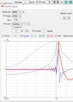
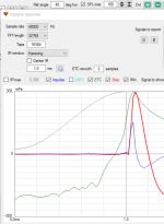
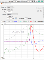
This stuff can be seen in impulse responses of spinorama data. If waveguide is rotation axis is at mouth, the impulse gets early within listening window as explained above. If rotation axis is at acoustic center the impulse stays where it should, within the listening window.
https://www.desmos.com/geometry/zmwyitoecg

It's missing waveguide profile though, and how it would increase path length beyond ~nominal coverage angle, but this doesn't affect things in listening window so not the most important thing here, sorry, my inner desmos wizard isn't that good so you just have to imagine how the waveguide would further affect path length 😀
What the test kind of suggests is that if waveguide is deeper than say 1/4wl at crossover, the waveguide should be brought forward toward listener so that it's acoustic center is about within 1/4wl to the woofer's in order to maintain smooth response at crossover in the listening window. This might look a bit silly with deep devices, hence attempt to make shallow waveguide. What I'm after is that even though the waveguide has ideal performance toward listening window it can be ruined around crossover if acoustic centers are too far apart.
As evident playing with Desmos example, if mouth is at baffle plane so that waveguide acoustic center is behind the woofers, the waveguide effectively comes closer to observer as angle starts to increase from 0, which makes dip in off-axis response if phase difference gets beyond 90degrees because waveguide impulse arrives before woofer's, so ideally it needs to be within 1/4wl and preferably less assuming broad listening window is wanted to be flat, as it ideally would, impulse from waveguide should arrive at the same time as woofer's. Listening window is the most important thing, so waveguide that is brought forward would compromise high angles, but those aren't that important as listening window. Math person could likely calculate what the max distance between acoustic centers could be to have smooth +-60 deg or so, +-90deg, at least as much as is the practical constant directivity target.
edit.
This stuff can be seen in impulse responses of spinorama data. If waveguide is rotation axis is at mouth, the impulse gets early within listening window as explained above. If rotation axis is at acoustic center the impulse stays where it should, within the listening window.


Last edited:
One more line for the practical constant directivity. How wide it should be? I said the -1db zone should be as wide as possible, but another way to look at it would be from the time / intensity trading thing as per Geddes. Assuming 45deg toe-in and ~15deg listening axis on equilateral stereo listening triangle, so that center image stays center when directly in front of either speaker so at 45deg listening angle frequency response should be very similar to 15deg angle (same response at for whole sofa), and what -6db difference between them for good time intensity trading? This is basically nominal 90deg ~device, 45deg -6db down with ~flat response. This would likely do the waist banding though, so 15deg / 45deg frequency responses would not match perfectly, so just some compromise there abouts.
Other aspects that affect are double listening spot thing I've been into, one close one bit further, but I have no ideal for this yet. Also room dimensions and practical positioning would affect what's the ideal coverage so ideal is somewhere there, perhaps any reasonable smooth coverage works just fine for most situations.
Other aspects that affect are double listening spot thing I've been into, one close one bit further, but I have no ideal for this yet. Also room dimensions and practical positioning would affect what's the ideal coverage so ideal is somewhere there, perhaps any reasonable smooth coverage works just fine for most situations.
Last edited:
One more aspect for "ideal" waveguide: I posted an example on another thread how matching DI of waveguide and woofer makes bump in system DI. This could be adjusted with c-c but also by making waveguide vertical directivity collapse bit earlier than the horizontal, which means asymmetric waveguide. This would likely help with vertical early reflections and thus be potentially better than an axisymmetric device in home use, although perhaps system DI is not that important as sound toward the specular early reflections so maybe this is not that important a thing, not sure, likely different for different applications / environments. This would also look weird, as c-c still needs to be maintained high for smooth system DI. Nevertheless someting to consider if one wants to juggle all things.
Juggling all things would include loading as well, which reduces with shallower devices but the throat extension you've been using likely puts the acoustic center forward while still adding loading, so is a good thing in this context I'm framing.
Juggling all things would include loading as well, which reduces with shallower devices but the throat extension you've been using likely puts the acoustic center forward while still adding loading, so is a good thing in this context I'm framing.
Last edited:
As for your post #15,981, honestly I don't follow much of it. How do you define acoustic center of a waveguide? To me, what happens behind the mouth, i.e. how deep is the horn, is irrelevant, as long as it can be compensated on the signal level, e.g. by delaying the woofer. I think you can imagine the wavefront at a mouth of a waveguide as if it was a diaphragm or a pulsating cap. Then you can think about how to best align those two diaphragms (woofer and the WG mouth), both in space and time, always having the option of adding delays.
I don't think I completely agree with the other posts, but this would get too elaborate...
I don't think I completely agree with the other posts, but this would get too elaborate...
It's simple trigonometry, lets simplify acoustic center is at throat of a device. If you see the throat of the waveguide, and start to rotate the waveguide keeping center of mouth as rotating axis, equidistant to you, the throat gets closer to you with increasing angle until you don't see the throat anymore it gets behind the corner and it gets further now. Path length from throat to you first shortened, then increased when rotation is ~beyond nominal coverage. If you repeat the same test rotating axis at the throat, the throat stays equidistant to you, until it gets behind the corner and you don't see it anymore, after which it gets way further with increasing angle.
Take spinorama data to vituixcad, open the impulse response window and scroll the ref angle to see the impulse move indicating distance to acoustic center changes. Now repeat this same for your woofer, the impulse stays ~still. Now, depending on whether your rotating axis is same or different than thewoofers, distance to waveguide changes differently, making phase difference to various angles changing frequency response = waistband if the difference in acoustic centers is too long.
Take spinorama data to vituixcad, open the impulse response window and scroll the ref angle to see the impulse move indicating distance to acoustic center changes. Now repeat this same for your woofer, the impulse stays ~still. Now, depending on whether your rotating axis is same or different than thewoofers, distance to waveguide changes differently, making phase difference to various angles changing frequency response = waistband if the difference in acoustic centers is too long.
Here example, A460G2 simulated with ABEC, rotating axis either at the throat, or at the mouth. Since z in vituixcad stays zero this means the rotating axis changes between the two at the woofer or behind the woofer, right
Here horizontal response with 500Hz crossover, if mouth is at baffle plane, when the acoustic centers are not on same axis:
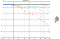
Destructive interference increases toward off-axis due to distance to waveguide acoustic center changing, while distance to woofer doesn't.
Here exaclty the same setup, except now the throat is at baffle plane, so same rotation axis for both devices. Now there is no destructive interference, as both acoustic centers are equidistant to the observer at all angles.
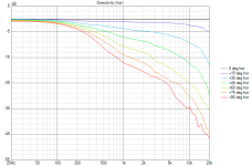
In practice, your complete system would measure like the first image if you put the device mouth to baffle plane, and the second if you put the throat to baffle plane.
Here you could use digital delay to compensate it to some direction, but that's electronical correction so affects all directions at once.
I'd appreciate if others confirm or bunk this, my data could have error, although it seems to behave logically 🙂 I'll do measured spins later, no finished system at yet.
edit.
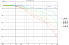
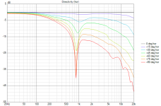
if crossover frequency goes up, here 1000Hz, the path length difference really shows up and severe destructive interference happens, if device mouth is at woofer plane. First image again waveguide throat is at woofers rotation axis, and the second one is when waveguide mouth is at woofers rotation axis.
Here horizontal response with 500Hz crossover, if mouth is at baffle plane, when the acoustic centers are not on same axis:

Destructive interference increases toward off-axis due to distance to waveguide acoustic center changing, while distance to woofer doesn't.
Here exaclty the same setup, except now the throat is at baffle plane, so same rotation axis for both devices. Now there is no destructive interference, as both acoustic centers are equidistant to the observer at all angles.

In practice, your complete system would measure like the first image if you put the device mouth to baffle plane, and the second if you put the throat to baffle plane.
Here you could use digital delay to compensate it to some direction, but that's electronical correction so affects all directions at once.
I'd appreciate if others confirm or bunk this, my data could have error, although it seems to behave logically 🙂 I'll do measured spins later, no finished system at yet.
edit.
if crossover frequency goes up, here 1000Hz, the path length difference really shows up and severe destructive interference happens, if device mouth is at woofer plane. First image again waveguide throat is at woofers rotation axis, and the second one is when waveguide mouth is at woofers rotation axis.


Last edited:
But that's not very helpful. For example, adding a 140mm throat extension to the A460G2 (as with the BMS 4554), this virtually doesn't change the polar pattern. The only thing it effectively does is adding a simple (one-dimensional) delay. Nobody would shift the acoustic origin (center of rotation for polars) to the new/extended throat, because that's not a change that would really matter. Just add a delay to the woofer and you're done, you have your short(er) waveguide back, keeping the mouth where it was for the best overall polars of the system.It's simple trigonometry, lets simplify acoustic center is at throat of a device.
Simply align the mouth relative to the woofer. Forget about the throat, that's basically delay-compensated where needed.
Last edited:
I think the extended throat does not move the acoustic center in this regard, hence I think it works just fine. It's the "shortcut" from "throat", where the waveguide/wave starts to expand, and this point moves faster with rotation if it's behind rotation axis.
That seems like overthinking to me, too. Although I didn't try to detect it, I also didn't observe a shift between tweeter and woofer on off-axis measurements.
I'm not sure we follow each other. It matters where the mouth is relative to the woofer, but the basic delay in the horn (if there's any) just needs to be compensated on the signal level, otherwise it will never work quite right.
You can't "align" the "throat" of a horn with the woofer's acoustic center and hope for good polars. But I think that's clear.
You can't "align" the "throat" of a horn with the woofer's acoustic center and hope for good polars. But I think that's clear.
Yeah that's what I've been thinking too that all that matters is wave at the mouth, but this data really shows it's not the case, so the data must be wrong or we are thinking it wrong? If real measurements of systems don't show this, then it's the data I use from ABEC / VACS.
Issue is not with idividual spins of either waveguide or woofer, and one could do them any way they want, but when they are combined as a system the issue shows up depending on how the waveguide is aligned to the woofer. Since the "waveguide" source gets closer with angle, the sound would need to delay within the device to come out at the same time as woofers to increasing angle.
I try to improve the Desmos visual to make it more logical to eye and better illustrate what I'm after.
All it matters is how the mouth is aligned to the woofer. They should be on the same vertical axis for the best possible horizontal polars, I would think. The rest is just a delay compensation. Vertically, that's a separate issue.[...] but when they are combined as a system the issue shows up depending on how the waveguide is aligned to the woofer.
I still don't understand this notion. Why should it get closer with angle?Since the "waveguide" source gets closer with angle
As I'm still not familiar with VituixCAD (at all), it's difficult for me to follow what exactly he did. But this must be independent of any tool, if it's something real. And I'm still having problem to understand what's the issue.
That's true, but if I remember his own words correctly, Earl originally made the speakers flat, thinking this was the best setting. Only then it was realized that it sounded too bright, and added the downward slope (again, the question remains why it sounded too bright). And as the speakers were, there was no other choice but to downward the slope of the power response AND the direct sound as well. What if he had the opportunity to keep the direct sound flat but add a slight upward slope to the DI? 🙂 That's the experiment that's still missing. Both ways have theoretical pros and cons, that's why it's not clear what's better. It can also be that the final audible differences are so small that all of this is just a noise...Incidentally, "a gently downwward-sloping power response AND a direct sound with the same, or a very similar, gentle downward slope" is what Earl Geddes was doing twenty-something years ago with the Summa, via his recommended 20-degrees-off-centerline listening axis.
Here updated Desmos to illustrate it directly without VituixCAD 😀 https://www.desmos.com/geometry/piyepl4o5g
If acoustic center of waveguide is at the throat,
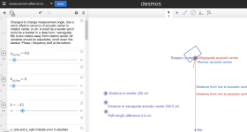
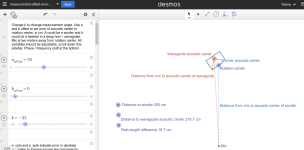
Here is link, hit play button for the k -variable on left to start rotating sequency. Move waveguide position by changing the a_offset slider, the first one. the labeling shows distance from both acoustic centers to mic.
When the waveguide acoustic center is behind woofer acoustic center, the waveguide acoustic center gets "closer" to mic with rotation, while woofer stays at one distance.
You could do it the other way around, rotate from waveguide acoustic center, but now distance to woofer changes per rotation. Or split on the middle and both change.
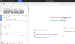
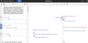
Implication of this is that at crossover frequency, where both have acoustic output, they will superimpose differently to various angles. The closer acoustic centers are at same axis, the better they constructively sum to ~all important directions. If one wants this, the waveguide must be positioned bit silly on top of the woofer, throat at baffle plane mouth way beyond baffle, like in the very first image on this post.
If acoustic center of waveguide is at the throat,


Here is link, hit play button for the k -variable on left to start rotating sequency. Move waveguide position by changing the a_offset slider, the first one. the labeling shows distance from both acoustic centers to mic.
When the waveguide acoustic center is behind woofer acoustic center, the waveguide acoustic center gets "closer" to mic with rotation, while woofer stays at one distance.
You could do it the other way around, rotate from waveguide acoustic center, but now distance to woofer changes per rotation. Or split on the middle and both change.


Implication of this is that at crossover frequency, where both have acoustic output, they will superimpose differently to various angles. The closer acoustic centers are at same axis, the better they constructively sum to ~all important directions. If one wants this, the waveguide must be positioned bit silly on top of the woofer, throat at baffle plane mouth way beyond baffle, like in the very first image on this post.
Last edited:
I meant basically the difference between A460 (rising DI) and A460D (flat DI). The latter has considerably worse frequency response per se, also the LF extension suffers to a degree. That's the biggest price, IMHO, but of course you gain the almost perfect constant directivity. It's pretty expensive though 🙂Hi Mabat,
I'm probably trying to keep up well outside my knowledge level:
The "price to pay" here is the drop at 17k hz?
Probably not, as BMS seem much more capable drivers when used with a long throat. It's just the extraordinarily nice response of the DFM with the A460/Gen2 waveguides that makes it so attractive, given its cost.If I'm following correctly the BMS will allow 800 - 20k hz CD in a single driver, the DFM-2535 allows 800ish to 17k hz.
Is there a reason you'd chose the DFM over the BMS then?
OK, thanks. That's what I meant by the wrong way how to look at it 🙂Here updated Desmos to illustrate it directly without VituixCAD 😀 https://www.desmos.com/geometry/piyepl4o5g
You should measure the distance to the mouth, not the throat, IMO. And compensate the distance from the throat to the mouth by adding a corresponding delay to the woofer, in principle.
Nice Desmos script, BTW.
- Home
- Loudspeakers
- Multi-Way
- Acoustic Horn Design – The Easy Way (Ath4)