I'm fully occupied now with the new segmentation - just love it 🙂


Last edited:

I'm not sure how important it is to have a such flat area on the back side of a waveguide for mounting a midrange.The middle part of the R-OSSE horn is pretty flattish - if there is no other way, the middle part petals could be machined to be slightly curved on the inside while keeping the outside flat to be able to mount the MF and LF drivers easily. I need ca 45 cm of flat surface on the outside, the rest can be whatever.
I was able to massage a pair of 4" Celestion TF0410MR on the back of a variant of the ST260 with decent results.
I have not worked on this in some time now but it can be done.
Here are some pics of the 3d work and a measurement:
Back:
Front
Cross section
Back sans mid
Response
Mids are not an issue, it is the 12" woofers used for lows - so that the port is not too long. If you look at the cross section you posted, I was referring to the driver mounting interface - which would need to be machined from the outside as well...so having a flat panel to mount the drivers makes it easier.
I did some more simulations and the dip is almost gone. I made a simulation without the roundover - that looks like a nightmare, but does not measure that badly.
All that said, if I will be able to find a set of parameters for a 95 cm diameter horn with a relatively flat area in the middle, I will go for fully curved layered construction. It is a lot of work, so the profile must be worth it.
Don Keele described the expected "waistbanding" problem with conical horns in his his "What's So Sacred About Exponential Horns?" paper back in 1975.That looks exactly as I intended. What surprised me were the results:
Is this to be expected from this type of horn? Especially the dip and peak below and above 1 kHz on axis. The configuration is attached.
The (partial) solution which has been adopted by many, as in Tom Danley's Unity and Synergy horns is just as Don described, approximately the last third of the conical horn angle is doubled.
Relatively easy to make from flat material, relatively constant directivity, but not very good in comparison to other designs.
Anyway, as Mabat has proven, horn design has come a long ways in the last 50 years, conical limitations are not worth pursuing now if you want to make a constant directivity horn.
Art
I have used similar products and agree with ElEsido, the expansion rates can blow things up (or be short), and the stuff is nightmarishly messy. Like tear off your skin, throw away your clothes, try to sand off the "blob" that wrecked your project..Has anyone tried to print petals with a sparse gyroid infill (which is porous all the way through) and then fill with a SmoothOn's FOAM-iT ("Castable Rigid Urethane Foam")?
The best results I've heard were using microballoons:
Used this type of stuff for damping some large fiberglass bass horns (half a box truck wide), too expensive for the quantity required but super inert.
The fiberglasser got the ratio of polyester to microballoons backwards, had one super heavy pair of horns.
Then used a kind of lightweight fibrous sheet wood product glassed on for damping on the next 16 horns.
Good damping, and light weight, but the fibers started falling apart and some rattles started to occur.
That cheap short-lived material has been withdrawn from the housing market..
Cue the nightmare foam fill attempt on one of the low-mid cabinets (start small) to hold the fibrous sheet in place..
After trying that on one pair, hired a professional foam-in-place packaging company to do the rest with their special mix in the wand fill tools and experienced crew.
After about a year replaced the system with a far more compact two box system using plywood bass & low mid horns with fiberglass mid and high horns, the latter being based on Don Keele's two part conical designs.
Art
Thanks, OK, I'll let the foam idea go. I've never worked with the glass microballoons - doesn't it make the mixture too thick to be still pourable?
Now this calls for a wysiwyg approach 🙂

(I've added an "Alternative transformations" paragraph: http://www.at-horns.eu/seg-horn.html)
(I've added an "Alternative transformations" paragraph: http://www.at-horns.eu/seg-horn.html)
Last edited:
Microballoons make the mixture lighter, but indeed less viscous. If you want significant weight savings you have to mix so much micro in the resin that it gets the consistency of peanut butter - no longer pourable (and brittle when it's hard, and micro balloons are somewhat tricky to work with as they go everywhere...). OTOH this application here is not weight critical - quite the opposite, weight might even be beneficial as the horn's mass acts against the driver's movement. I would't bother about the weight of the filling and just pour pure resin into it and use a suitably strong stand/mount. I plan to do some tests this weekend...Thanks, OK, I'll let the foam idea go. I've never worked with the glass microballoons - doesn't it make the mixture too thick to be still pourable?
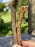
I don’t think I mentioned this here but this summer I made a couple tests where I took a vinyl hose and filled it with dry fillers of different grain size and material (sand, cork grains) and introduced epoxy from the top and watched how different types of epoxies performed when it came to penetrating and displacing the air from the top.
And a low viscosity infusion epoxy hardened with a slow setting catalyst together with filter sand 0.4-0.6mm grain size worked as intended.
Also cork grains with the same epoxy. (Highly damped composite material)
I have an idea that one could incorporate a printed tube that goes thru the bed of filler material that has micro perforations that won’t get clogged by the filler but will let the epoxy flow in to the material of choice. Like an infusion supposed to work but without the vacuum.
But haven’t tried it.
Edit: https://www.easycomposites.eu/in2-epoxy-infusion-resin the winner.
Attachments

Last edited:
I am not completely sure what you guys are looking for, just wanted to share that PVA can be made pourable by mixing with water.
To make the printed structure better damped (personally, I'd prefer as lightweight solution as possible). But I think that the thickness itself helps a lot.I am not completely sure what you guys are looking for, ...
STLs updated for the ATH330EX (in a knock test it seems fine; also the wall itself is not thin) -
Last edited:
... when I say thickness, I mean the overall thickness of the waveguide, not just a single (printed) wall of the outer shell.
It is 1/2 - 1" in this case, I think. The shell itself is only ~1.2 mm (two perimeters for 0.6 mm nozzle) - I didn't try more, perhaps it would help as well.
And of course it must be pourable (low viscosity) in this case. The petal could be printed even with some hole(s) and prepared funnels on top...
- Still thinking about it, I'm probably going to try the F@#k-iT foam anyway 🙂
Last edited:
I have printed waveguides with 9-10mm thickness and 100% infill before, and saw no difference in measured behaviour compared to just a decent amount of wall loops (3-4 with a 0.4mm nozzle) and 15% infill density. It seemed to be a waste of filament to me, but I still did it for peace of mind after the prototypes showed good results.
That's what I would think. The infill inside seems to be pretty good for damping, actually. The idea is that it just leaves a lot of voids to be filled with something even better (or not)... For this reason, I use gyroid infill all the time (<10 %), just in case.
The other thing is if we are even able to measure/verify the effect. Do we even know what to look for, other than an obvious knock testing by ear? 🙂
Should it have an effect on intermodulation (multitone) distortion, for example?
In the real operation (i.e. reproducing music), what makes the waveguide deform in the first place? Is it the compression driver, its (even if miniscule) vibration or even the sound radiated? Or is it more the rest of the enclosure? To be honest, this is still not clear to me. What's supposed to be the strongest effect?
Maybe making a really flimsy waveguide would help...
Last edited:
It is not me who called it MK1 and MK2 😉 but yes it would be great if you can add a simpler model similar to MK1: graph performances of MK2 look slightly better to be.MK1 is just a different device, that doesn't make much sense to me. But I can update the MK2 by adding a simpler model, similar to MK1 😉
BTW, I think I've found a way to measure HOMs in an OS waveguide directly -

With the help of IR gating, there should be plenty of time to capture the high frequencies in detail.
The top cover is of course in the shape of the main mode.
Could be probably used at least to compare/assess different drivers in the amount of HOMs they produce.
With the help of IR gating, there should be plenty of time to capture the high frequencies in detail.
The top cover is of course in the shape of the main mode.
Could be probably used at least to compare/assess different drivers in the amount of HOMs they produce.
Instead of several mics I would make it with only one mic in a sliding part. That would eliminate the need of mic matching and also allow for a free positioning.
How will you analyse the measured response? How do we expect the HOMs to be discerned?
- If we have infinite spatial resolution, there will be certain frequencies that show pressure nodes across the radiating surface, the horn mouth.
- Echoes in the impulse response at certain angles.
- Hash/noise in the frequency response when comparing to simulations at certain locations.
- Home
- Loudspeakers
- Multi-Way
- Acoustic Horn Design – The Easy Way (Ath4)