.....
How did you come up with -40 dB?.
-40dB is equal to 1% harmonic distortion so going bellow it pushes the problematic area in to the realm of very low subjective perceivability.
Last edited:
Experience is nice, but it must be formalized if it should help with modeling. This is why I was asking.
I don't quite understand what are you trying to get at here. I see it as simple - moving the crossover frequency lower, if the HF device allows so, just makes sense to me, no matter what all the numbers are in any particular case.
Too often these designs work on the edge of feasible. It's nice to have it a bit more relaxed, especially from the designer perspective. We want to enjoy it, don't we - designing crossover should be a joy, not a nightmare 🙂
Last edited:
Yes, sure. Let me explain: Setting formal criteria makes it possible to easily try and identify if a measurable characteristic can be perceived. If I continue from my previous example, the PHL 3411: when crossing it at 1.25 kHz, its breakup resonance at 2.7 kHz should be down ~30+ dB after EQ-ing the response to flat. I cannot identify it when listening to music. This might be due to a lack of experience, that is, I would not even know how this breakup resonance sounds, or that it is not noticeable. This is why I am asking.
It's possible that the PHL 3411 is good enough. I just say it's often a bit "tight" around the crossover and I think that if you showed us the measured data for both LF and HF it would be obvious. There are probably no rigorous quantities of what's "good enough". If you don't hear it, it's certainly good enough for you (and I believe the 3411 is usable this high).
Last edited:
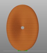
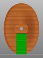
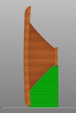
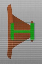
It's doable but you would need supports inside the throat -


But the 3D printers are getting better and better..
BTW, all the three variants would take about the same time. I like the first one as there are no supports on the front face.
But the 3D printers are getting better and better..
BTW, all the three variants would take about the same time. I like the first one as there are no supports on the front face.
Last edited:
How deep is the Waveguide?I'm working on a something like the ST260 but with an LF extension...
I print a cap on the back of the throat that I later remove with a tiny saw.It's doable but you would need supports inside the throat -
View attachment 1222151 View attachment 1222152
But the 3D printers are getting better and better..
BTW, all the three variants would take about the same time. I like the first one as there are no supports on the front face.
- Perhaps the hexagonal shape is too daring. I realized I can morph the mouth to round back again -


This is a 1.4" throat, ready to be extended...
This is a 1.4" throat, ready to be extended...
Does this shape have any theoretical advantage over a "round" one? Maybe it supreses ring/bell resonance better?
//
//
I don't know but it works extremely well. It could have an odd number of segments, maybe that would be even better, it's just a pain to simulate.
- BTW @miero has added an interactive 3D R-OSSE model into Desmos: https://www.desmos.com/3d/2e5f28c33b
- BTW @miero has added an interactive 3D R-OSSE model into Desmos: https://www.desmos.com/3d/2e5f28c33b
Last edited:
I don't know the right terminology, but, is it possible the segments work somewhat like the 'ticklers' that were discussed some pages ago? like the shape near the throat of the waveguide in the JBL M2? Just more discreet?
I'm also remembering the pods that were put on the cone surface of (RCA?) studio monitors in the 1950's. IIRC it was a coax. Memory is fading.
I'm also remembering the pods that were put on the cone surface of (RCA?) studio monitors in the 1950's. IIRC it was a coax. Memory is fading.
It's doable but you would need supports inside the throat -
View attachment 1222151 View attachment 1222152
But the 3D printers are getting better and better..
BTW, all the three variants would take about the same time. I like the first one as there are no supports on the front face.
I've found that there are infill patterns which are far more forgiving of overhangs. I need to look up the name of the infill. It looks like a jigsaw pattern.
Someone on Reddit showed something comparable to this infill, which allowed them to nearly print horizontal surfaces with little or no supports.
I use it for nearly everything now. Besides being forgiving, the complex pattern also sticks like crazy on the first layer, which basically eliminates nearly all print failures.
I'm trying to simulate an on-wall speaker with ATH using an R-OSSE profile.

I would expect this to give a very clean response and even dispersion. There will be hardly any reflection off the wall. However, this is the result:

This is the script:
Any idea why this doesn't work?
I would expect this to give a very clean response and even dispersion. There will be hardly any reflection off the wall. However, this is the result:
This is the script:
Code:
R-OSSE = {
   R = 155        ; waveguide radius
  r0 = 8        ; throat radius
  a0 = 5        ; throat angle
  a = 21.7        ; nominal coverage angle
  k = 1.7        ; throat expansion factor
  r = 0.98        ; apex radius factor
  b = 0.795            ; bending factor
  m = 0        ; apex relative position
  q = 3.21        ; throat weighting factor
  }


Mesh.LengthSegments = 60
Mesh.AngularSegments = 8
Mesh.SubdomainSlices =
Mesh.WallThickness = 5
Source.Shape = 1
ABEC.SimType = 1 ; 1= infinite baffle, 2= freestanding
ABEC.SimProfile = 0
ABEC.MeshFrequency = 43000
ABEC.NumFrequencies = 100
ABEC.Abscissa = 1
ABEC.f1 = 200
ABEC.f2 = 20000
ABEC.Polars:SPL = {
 MapAngleRange = 0,180,37
 NormAngle = 10
}
Output.ABECProject = 1
Output.STL = 0

Report = {
Title = IB
Width = 1600
Height = 900
GnuplotCode = rcirc-mono.gpl
MaxRadius = 180
MaxAnglePM = 180
}
Any idea why this doesn't work?
In fact, it works. It's just what you've created (and it's not really a waveguide) -Any idea why this doesn't work?
Don't set m = 0.
https://www.desmos.com/calculator/qpd6yfvf9b
Anyway, for baffle mounting, I'd use OSSE instead.
- Home
- Loudspeakers
- Multi-Way
- Acoustic Horn Design – The Easy Way (Ath4)


