Mylar would be better.BTW, it's possible to buy the sole diaphragms+coils for (e.g.) the D2500Ti. What could one expect when clamped this between two rubber rings? Wouldn't there be some advantage over the stiff surround for home use? That's what I intuitively feel but maybe it's not a good idea (?) so it's not even worth a try.
View attachment 1214606
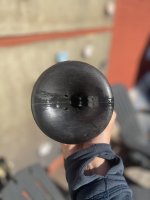
This looks like it, but it's the 3" brother:
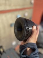
Aftermarket alternative (1.75"):
Last edited:
Yes sir !!!There's simply something to the "full-bodied" reproduction from one driver. You won't hear that very often.
Your current horn project graphs look awesome 🙂There's really a great potential in using large-format drivers at their phase plug exits, even if radiating e.g. through a 1.4" aperture.
If we can reach 500 Hz with such an ease, there's really no reason for any MEH or something, IMO.
If I may humbly suggest...why stop at 500Hz?
Why not try to take "full-bodied" reproduction as low as we can? Make it even more "full-bodied"?
In my mind, this is the reason behind a unity/synergy/MEH.... take the idea of "full-bodied" reproduction as low as possible.
To date, that unity/syn idea has been compromised with the need to make mounting surfaces that work for larger drivers on horns that have less than the excellence your horns, OS horns etc., have been able to achieve for the top half of the audio spectrum.
Horns like yours and OS nail the top half of the spectrum imo...and you've got it reaching into the upper end of the bottom half of the spectrum now, at 500Hz.
I have horns that can get my CD's to reach to below 500Hz, (with good response, but they are surely not as refined as your postings).
My experience so far, is full spectrum integration ala unity/syns has beared more fruit than mainly trying to optimize the top half.
But If you guys can figure out how to integrate your exemplary designs with additional drivers below the CD, and integrate the lower half of the spectrum into a single horn....
i say go man go !!!!!! And go some mo' !!! I'll do my best to build such.

Isn't this the easy part now? BTW, what is the minimal cross-section area requirement for the MEH ports for a given low frequency limit? Say 100 - 500 Hz, at home levels of course.
Last edited:
Yep, and the easy part is looking really good !
I figure lower frequency port size is mainly about what is the SPL design goal. Which of course also begs, what size drivers are being used.....
I try to have all driver sections including the CD, run out of steam at near the same SPL. So pretty high SPL designs (for the sake of maximizing normal listening level sound quality)
Need to get all that out, to explain my perspective....
Anyway, using a couple of 10"s in a build which can reach straight to CD at 500Hz, and was designed to cross to a sub at 100Hz....
each of the 10" gets a port with around 40 cm^2 area. About an 8:1 ratio, driver Sd to port area.
https://www.diyaudio.com/community/threads/syn-10.383607/#post-6963151
I think smaller drivers, if they can reach to 100Hz at desired max SPL, could probably use a higher Sd😛ort ratio.....further minimizing port areas.
But port noise at SPL would need to be tested.
Minimizing port length (thru the horn walls) is supposed to help increase flow.
It's one reason I've always had a hard time picturing how to mate lower frequency cones onto anything other than a flat horn wall.
Seems like ports would have to be longer ducts (than just thru a flat horn wall) to feed into curved horns, and therefore need greater cross sectional area to accommodate equal flow. Seems to work against minimizing port areas and potential horn disruptions.
By the easy part I meant the integration of the ports. At 500 Hz the 1/4WL is roughly 17 cm (6.8"), that should be comfortable enough to work with. With the hexagonal approach the walls are virtually flat after a few centimeters. I can easily imagine adding three 16-ohm drivers to an existing design, could be 8" I guess, maybe smaller.
Last edited:
you won’t give up on your redcatt coaxial, right?
I’m so curious and hopeful about it.
This is where I’m at with the little one.
Close, but not done yet.
I’m so curious and hopeful about it.
This is where I’m at with the little one.
Close, but not done yet.
Attachments

I assume this is a passive cardioid design.
Sidelobes in the 1k region might be caused by resonances in the enclosure.
Playing around with damping material behind the cardio ports might improve things.
Super nice design!
Sidelobes in the 1k region might be caused by resonances in the enclosure.
Playing around with damping material behind the cardio ports might improve things.
Super nice design!
I haven't started yet. Too much to be done before it's too cold outside.you won’t give up on your redcatt coaxial, right?
- I want to finish the big concrete horn this autumn, at last, I have it almost ready to be casted.
I hope you will describe the whole concrete casting process a bit deeper!?
//
//
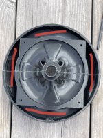
You’re assuming right and you are exactly right on what the plan is for the future.I assume this is a passive cardioid design.
Sidelobes in the 1k region might be caused by resonances in the enclosure.
Playing around with damping material behind the cardio ports might improve things.
Super nice design!
There is melamine foam in the whole back enclosure, but nothing between the cone and the opening on the sides. So the space marked in red is next to be experimented on.
Attachments
Gotcha.By the easy part I meant the integration of the ports. At 500 Hz the 1/4WL is roughly 17 cm (6.8"), that should be comfortable enough to work with. With the hexagonal approach the walls are virtually flat after a few centimeters. I can easily imagine adding three 16-ohm drivers to an existing design, could be 8" I guess, maybe smaller.
From looking at the hex horn's picts, I thought there was more curvature than you are saying, that would still be hard to mount to.
The hexagonal shape allowing drivers is very interesting. I really hope someone gives this a try.
I use Really from Kvadrat for the resistive ports.You’re assuming right and you are exactly right on what the plan is for the future.
There is melamine foam in the whole back enclosure, but nothing between the cone and the opening on the sides. So the space marked in red is next to be experimented on.
It's pretty flow resistive 70% fabric and 30% polyester compressed material and does a perfect job.
https://www.kvadrat.dk/en/really/solutions/textile-felt
A good exercise is to do a close mic measurement of what comes out of the ports.
You only want sub 1000 Hz frequencies, since the horns takes care of directing everything above that.
When high frequencies come out of the ports they mix up with what comes out of the horn and create the pattern you see.
It's quite nice already!
Just find something with more flow resistivity and put it there against the holes. Make sure air doesn't go around the material, but through it.
I have a few materials in mind, but was initially hoping that I would be able to print a micro perforated surface that would be more precise and reproducible than various stuffings and flow resistance materials.
Is it possible to use ATH to simulate a fully "source defined" axisymmetric enclosure? I've drawn a spherical enclosure for a coax driver in CAD but exporting it to Akabak for each iteration feels slow. Simming a quadrant seems to work though I can't seem to input arcs in the rear correctly ("control points are not cocircular" no matter what I do) but axisymmetric would of course be nicer


It's possible to add a user-defined rear spline (cubic Bézier) to a waveguide (with or without a user-defined source, that doesn't matter):
https://www.diyaudio.com/community/...-design-the-easy-way-ath4.338806/post-7228432
If it's axisymmetric, I'd suggest to use an axisymmetric model as well, it will be much faster.
https://www.diyaudio.com/community/...-design-the-easy-way-ath4.338806/post-7228432
If it's axisymmetric, I'd suggest to use an axisymmetric model as well, it will be much faster.
Problem is, I also have the waveguide user-defined. I can match a small R-OSSE and a Bezier to the coaxial profile but it's kinda burdensome and I keep failing to make the Bezier work from the Desmos script anyway...
It seems I got axisymmetry to work though with the whole thing user-defined, and meshing problems I had are gone. The enclosure in ABEC however looks pretty rough to me and there doesn't seem to be a way to control the resolution. Not sure if that's screwing up the results or if I'm missing something else...


It seems I got axisymmetry to work though with the whole thing user-defined, and meshing problems I had are gone. The enclosure in ABEC however looks pretty rough to me and there doesn't seem to be a way to control the resolution. Not sure if that's screwing up the results or if I'm missing something else...
The looks don’t matter, axisymmetric is very high resolution.The enclosure in ABEC however looks pretty rough to me and there doesn't seem to be a way to control the resolution.
The enclosure in ABEC however looks pretty rough to me and there doesn't seem to be a way to control the resolution.
In my experience, resolution is normally at the end of the line. For example, 50 in the following line.
point P0 114.3 0 50
You can also control resolution in the mesh statements. (These might not be used in CircSym, I'm not sure.)
; -------------------------------------------------------
; Mesh Settings
; -------------------------------------------------------
Mesh.LengthSegments = 20
Mesh.AngularSegments = 20
Mesh.ThroatResolution = 64
Mesh.MouthResolution = 64
Mesh.SubdomainSlices =
Mesh.WallThickness = 2
Your simulations might be squigly due to your ABEC settings rather than resolution.
; -------------------------------------------------------
; ABEC Project Settings
; -------------------------------------------------------
ABEC.SimType = 2 ; 2= Free Space, 1= Infinite Baffle
ABEC.SimProfile = 0 ; 0 = CircSym
ABEC.MeshFrequency = 33000
ABEC.NumFrequencies = 100
ABEC.f1 = 500 ; [Hz]
ABEC.f2 = 20000 ; [Hz]
I don't always use high resolution for running simulations. I might only increase it to create the STL file for printing. If you post your config file someone could probably show you what to try.
Last edited:
Page 50 of User Guide.
In the CircSym mode the items defining the mesh resolution are ignored. We could leave them without any
effect, delete or just comment them out:
; Mesh.ThroatResolution = 4.0 ; [mm]
; Mesh.InterfaceResolution = 8.0 ; [mm]
Page 51 of User Guide
Figures 24 and 25 show the resulting circular mesh as displayed in ABEC. The number of profile points (P1 -
P20 in Fig. 24) is still controlled by the item Mesh.LengthSegments:
Mesh.LengthSegments = 20
In this particular example it seems high enough but generally the number of points (i.e. number of line
segments approximating the profile) can be increased greatly - we want a high mesh resolution anyway.
So it looks like Mesh.LengthSegments is what matters in CircSym.
- Home
- Loudspeakers
- Multi-Way
- Acoustic Horn Design – The Easy Way (Ath4)