Yes!That's better 🙂
Response looks more similar to EAW's charts now.

There's a pre-release implementing the 2-profile geometry on my website: https://at-horns.eu
(Ath-4.9.0, no docs yet, just a commented example included.)

Notes:
1) The horn included is not supposed to be an example of a good design (it's really bad), it only demonstrates the new functionality.
2) Understanding of the OSSE profile parameters is needed to utilize the new functionality.
(Ath-4.9.0, no docs yet, just a commented example included.)
Notes:
1) The horn included is not supposed to be an example of a good design (it's really bad), it only demonstrates the new functionality.
2) Understanding of the OSSE profile parameters is needed to utilize the new functionality.
Last edited:
OSSE parameter names unified with the latest Ath version: https://www.desmos.com/calculator/j9ms6czqrz
BTW, now you can use rectangular throat:
Horn.Adapter = {
Width = 28 ; [mm]
Height = 50 ; [mm]
Segments = 0
}

Horn.Adapter = {
Width = 28 ; [mm]
Height = 50 ; [mm]
Segments = 0
}
Hi,BTW, now you can use rectangular throat:
Horn.Adapter = {
Width = 28 ; [mm]
Height = 50 ; [mm]
Segments = 0
}
View attachment 1063415
Thanks for the update,
Did you change the box simulation i.e. export of both sources in one go?
This is how to simulate flat walls with a simple flat driver entry, i.e. without any throat adapter. And of course you can add any number of subsequent horn segments (a better mouth termination) you like (or make the walls of the first part already bended (OSSE), of course).

Code:
Horn.Adapter = {
  L = 0
  Width = 40
  Height = 40
  Segments = 1
}

Horn.Part:1 = {
  L = 150
  H = {
    k = 0
    a = 42
  }
  V = {
    k = 0
    a = 30
  }
  Segments = 1
}
Attachments
Last edited:
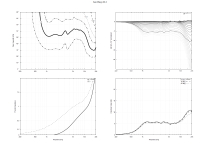
Just for completeness, these are the results -
(1.4" throat, HxWxD = 310x213x150mm, SPL for constant acceleration, polars 0 - 90 / 7.5)


(1.4" throat, HxWxD = 310x213x150mm, SPL for constant acceleration, polars 0 - 90 / 7.5)
I've tried designing such a device. You may want to adjust the parameters somewhat if you desire more gradually rising DI - I myself wanted to try constant 5-6 dB up to 16 kHz, but was not able to achieve this with a 25 mm dome and simple phase plug. Maybe there is something to be done about phase plug design, or maybe I have to bite the bullet and convert my direct radiating dome into a compression driver proper - with, say, 16 mm exit. Current PP basically does nothing aside from protecting the dome from pokey fingers and providing unusual throat impedance. Last 4-pack is the same WG with phase plug omitted.Can you also do WG/horn that are wide dispersion? If yes, did you ever present such a design here?
//
Attachments
As a side note the problem with missing SPL_h in VACS persist.
https://www.diyaudio.com/community/...he-easy-way-ath4.338806/page-421#post-6818233
Reports mostly provide the same functionality, but ability to export your horn straight into the VituixCAD would be very nice.
https://www.diyaudio.com/community/...he-easy-way-ath4.338806/page-421#post-6818233
Reports mostly provide the same functionality, but ability to export your horn straight into the VituixCAD would be very nice.
There is the FRDExport option now which does precisely that.Reports mostly provide the same functionality, but ability to export your horn straight into the VituixCAD would be very nice.
https://www.diyaudio.com/community/...-design-the-easy-way-ath4.338806/post-6996527
As Marcel gave us oportunity to design WG for rectangular source as AMT is I have tried to design WG for Heil AMT. Still not discover how to design Rollback (if it is possible) but what I get does not look so good.


Of course, I am not sure am I doing some mistake and could it be improved more. Below is attached script so if somebody have a will can check and advise.
Of course, I am not sure am I doing some mistake and could it be improved more. Below is attached script so if somebody have a will can check and advise.
Attachments
Any way, as I was not satisfied with results I wanted to confirm it in practice. I made some kind of WG arround Heil chasis from plastic folie, cardboard and duct tape. As You can see on photos finish is rough and with several flaws
.jpg")
.jpg")
.jpg")
.jpg")
but measurements are promising. Below measurements are ungated with 1/6 smoothing. First two are without any filters and second two with DSP and HP filter at 1 kHz


WG just follow V Heil chasis walls without any curve. I think with implementing OSSE things will get even better
but measurements are promising. Below measurements are ungated with 1/6 smoothing. First two are without any filters and second two with DSP and HP filter at 1 kHz
WG just follow V Heil chasis walls without any curve. I think with implementing OSSE things will get even better
Last edited:

Nice - cant beat reality 😉
And a more rigid "WG" would probably be a bit better as that will perhaps act as a membrane at certain frequencies...!?
//
And a more rigid "WG" would probably be a bit better as that will perhaps act as a membrane at certain frequencies...!?
//
This is what I get with the script provided -


I only changed the 2nd horn part a bit (not sure it makes a difference) -
I only changed the 2nd horn part a bit (not sure it makes a difference) -
Code:
Horn.Part:2 = {
  ...
  Segments = 16
  ;ZMap = 0.5,0.8,0.5,0.8
}No, that's not possible at the moment.Still not discover how to design Rollback (if it is possible)
Last edited:
I don't know. Sometimes it behaves in mysterious ways...
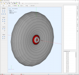
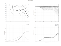
- I have to admit I'm attracted to the 2-profile geometry for a while now. I already have some bendable plywood which seems a great way to make these.
This one is 624 x 448 x 328 mm, 1.5" throat, simulated free standing (horizontal data only):


- I have to admit I'm attracted to the 2-profile geometry for a while now. I already have some bendable plywood which seems a great way to make these.
This one is 624 x 448 x 328 mm, 1.5" throat, simulated free standing (horizontal data only):
Last edited:
What happens to the directivity when stood off axis vertical and horrizontally at the same time (due to the square horn geometry)
Say 40 Deg X plain and 40 deg Z plain?
Can you simulate that?
And is that 624mm depth I take it?
I ask because I have a large format laser cutter and an application that fits this or somthing close.
+ An idea.
We all generally struggle for a way to easily make the best large format horn profiles.
If you started like this with a square mouth that is made from Flexi-ply and a laser cutter (cheap and very easy!- this would take 30seconds machine time)
Those that cannot access a laser can draw out the coordinates on the wood manually
You would have to check/be careful of the max Bend radius, (looks ok by my guess)
Throat can be 3D printed for transition from round compression driver profile to square horn, and bolting to different drivers (1.4 or 1.5 inch for example.
Then, for better response, add 3D printed inserts to the throat for improved response if needed (thinking JBL M2/klipsch fillets here)
You would have a universal horn system.
My driver is a JBL 2452SL 1.5 inch exit, 0deg exit angle driver. Aim would be to mate to a 15 inch bass driver, unfortunately I can't put the corner wall at 45degrees. I can check today, but it's more like 30.
In 3 weeks I have time to trial this for an in wall corner horn if that helps (or flat wall if it measures better- but side walls of the room are quite close.)
I have sole access to 10 3D printers + 1200x900 mm format laser cutter for 6 weeks. I'm fairly good with Autodesk Inventor too.
See my thread for details on the installation.... Post 1 and 26 for key information.
https://www.diyaudio.com/community/threads/jbl-m2-in-wall-clone.387176/
Last edited:
- Home
- Loudspeakers
- Multi-Way
- Acoustic Horn Design – The Easy Way (Ath4)