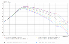
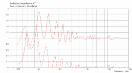
Ran a few quick simulations on my ND25FN project: looks like increasing the k factor alone doesn't really help on dome tweeters. I suspect much of this is due to the change in apparent coverage angle.
These simulations are based on the following OS-SE waveguide:
Length = 55 mm
Throat angle = 0 deg
Coverage angle = 90 deg
q = 1
s = 1
n = 3.5
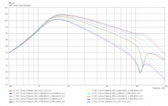
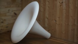
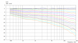
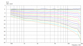
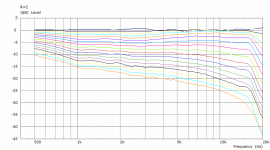
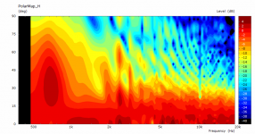
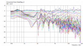
First image has k=1, second image is k=2, third image k=4.
These simulations are based on the following OS-SE waveguide:
Length = 55 mm
Throat angle = 0 deg
Coverage angle = 90 deg
q = 1
s = 1
n = 3.5
First image has k=1, second image is k=2, third image k=4.
Attachments
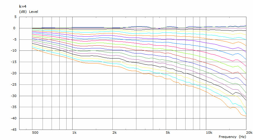
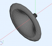
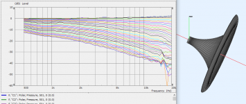
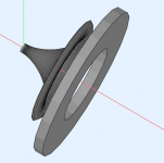
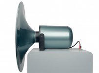
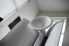
Quite a beauty")
Roundover is similar to this JMLC horn.
Should be good
And looking again at the polars, I think this maybe a keeper.
Perhaps with some minor tweaks here and there.
Attachments
Last edited:
The rollback shape in Ath is actually an Euler spiral, as I've realized when going through the code I quickly scribbled. Basically I unintentionally made a new way how to calculate it I'm quite happy with that. (The "bug" I reported before is not really a bug - it's a feature.)
I'm quite happy with that. (The "bug" I reported before is not really a bug - it's a feature.)
Last edited:
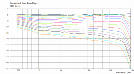
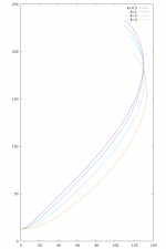
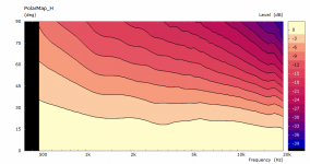
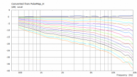
This is a little study of the "k" parameter (I call it an expansion coefficient). Basically by increasing the value you give up some of the constant directivity and get a bit of overall smoothness instead (and somewhat increased loading). It is for a 1" driver in a free stading waveguide of approx. ⌀400 mm, without chaning any other parameter.
Pure OS-SE-ES WG (k=1, this is about as good as it gets regarding CD):
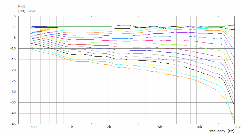
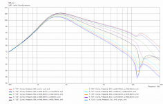
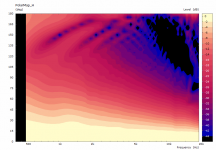
k=2:
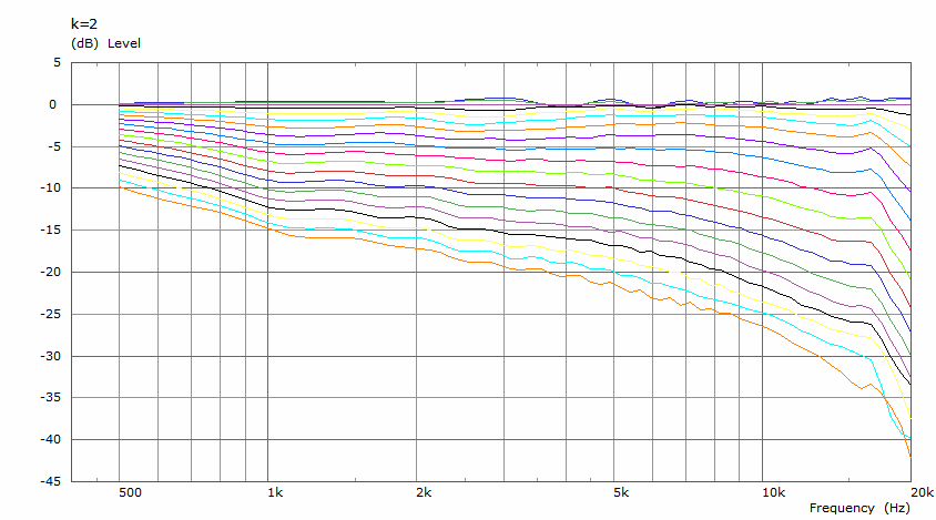
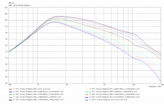
k=4:
Pure OS-SE-ES WG (k=1, this is about as good as it gets regarding CD):
k=2:
k=4:
Attachments

At the moment I consider those sims to be quite good approximations of the waveguides as if put into (rounded) enclosures, without the need to model the whole boxes. Obviously these are not meant to be used in flat baffles. If used free standing as they are, there's still to be found out how much detrimental will be the reflections off nearby objects, mainly behind the waveguides, and also the reflections and diffrations off the waveguides.
Last edited:
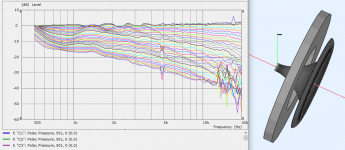
I tried the influence of an obstacle near the waveguide. It's not ideal but neither hopeless
What about a rectangular object (a cab) that only obstructs the bottom of the waveguide's rear?
Like this:
Attachments
Last edited:
- Home
- Loudspeakers
- Multi-Way
- Acoustic Horn Design – The Easy Way (Ath4)