
Both interfaces and woofer appear to be original and in very clean condition.
I do notice that the bias circuit is original, and it would be a good idea to update that. This update does not affect the sound of the speaker, but rather, improves its reliability. If nothing else, it would be a good idea to recalibrate the bias voltage, which WILL affect the balance between ESL and woofer portions. And in that respect, a slight adjustment of the bias voltage can also be used to tailor that balance to your liking. Instructions are attached, cost of parts is minimal.
I do notice that the bias circuit is original, and it would be a good idea to update that. This update does not affect the sound of the speaker, but rather, improves its reliability. If nothing else, it would be a good idea to recalibrate the bias voltage, which WILL affect the balance between ESL and woofer portions. And in that respect, a slight adjustment of the bias voltage can also be used to tailor that balance to your liking. Instructions are attached, cost of parts is minimal.
Attachments
Hi Andy,
Thanks, I am currently traveling and will look into updating the bias circuit when I get back home. I am looking forward to listening to these speakers.
Thanks, I am currently traveling and will look into updating the bias circuit when I get back home. I am looking forward to listening to these speakers.
Now that I am back home, I have had an opportunity to listen to the speakers. It turns out that there is no output from the woofers. I am going to have to take them apart to see what the problem is.
It turns out that the woofers have been disconnected. One of the previous owners cut the wires to woofers inside the box. I checked both woofers with my multimeter and got a reading of about 7 ohms for both of them.
The woofer is the 'weak link' in the Spectra 11, so I suspect the previous owner attempted to use an external woofer, probably with not very good results. Sounds like all you need to do is reconnect the wires and evaluate from there.
Thank you Andy.
I have some additional problems, has been repaired but still has some damage.


I have some additional problems, has been repaired but still has some damage.
Is that "blown up" damage, or merely mechanically damaged? I've never seen one of those caps "let go", but it's possible. Either way, it should be replaced with a similar non-polar electrolytic.
It looks like mechanical damage to me. It is a 50uF, 50V cap, the other channel has a 100uF, 100V cap in that position. The 220uF, 35V has also been replaced with 220uF, 25V cap and the 14M ohm resistor has been replaced with a 10M ohm. I am going to order some new parts so that I have matching components in both channels.
I agree with your idea to replace all the crossover caps. I would use 50-volt minimum rated non-polar electrolytics (higher voltage is okay). The value of the 10M-ohm resistor is not critical, its purpose is for safety ground isolation. But at the very least make them both the same value for your two speakers. Although 10M-ohm was the "standard" value, sometimes Acoustat substituted similar values when the 10M-ohm was not available.
Do you have a schematic for the Spectra 11?
Do you have a schematic for the Spectra 11?
I reconnected the woofers and they work so that is good news.
Received the new 100uF/100V capacitors and installed them, they are bypassed with Audio Note 0.15uF tin foil paper in oil capacitors. I am waiting for one more order to come in before I tackle the bias circuit.
Received the new 100uF/100V capacitors and installed them, they are bypassed with Audio Note 0.15uF tin foil paper in oil capacitors. I am waiting for one more order to come in before I tackle the bias circuit.
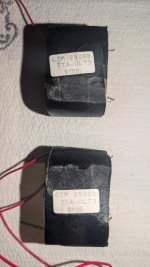
I am building a couple of the Spectra HV supplies from scratch. I was lucky enough to be able to buy two of the step up transformers when they were on Ebay a few years ago. I understand that the correct and final schematic is the one shown for the Spectra 11. I just wondered where the LED is connected since it is not in the schematic.
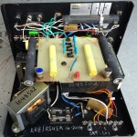
The other question I have is about the Airmod done by Roy Esposito. The high voltage transformer normally has two fuses one/leg on the AC in, but Roy has replaced one of the fuses with a resistor as in the picture attached. Just wondered if you knew why?
Thanks
Andrew
The other question I have is about the Airmod done by Roy Esposito. The high voltage transformer normally has two fuses one/leg on the AC in, but Roy has replaced one of the fuses with a resistor as in the picture attached. Just wondered if you knew why?
Thanks
Andrew
Attachments
The Spectra 11 was an ESL/woofer speaker, while the Spectra 22 was a full range speaker. The schematics are not same . Your pic is of a full range interface
I know that, I have both a 2+2 with the AirMod and some Spectra panels I am building a HV power supply for . I believe Andy in an earlier post said that the Spectra 11 schematic is the final revision of the HV supply regardless whether it is a Spectra 22 or 33. The two questions are for two different speakers
OK, sorry.
Memory serves me correct, the HV Bias circuit for the standard full range (not spectra 11) was a simple 5 stage voltage multiplier, while the spectra 11 interface had a very complicated HV circuit that always gave me issues (that one had an OPAMP oscillation circuit?)
Memory serves me correct, the HV Bias circuit for the standard full range (not spectra 11) was a simple 5 stage voltage multiplier, while the spectra 11 interface had a very complicated HV circuit that always gave me issues (that one had an OPAMP oscillation circuit?)
All Acoustat speakers (except for the very earliest models) use a 5-stage voltage multiplier for the HV bias. The difference is how the multiplier is powered. Speakers equipped with a mains cord have a step-up transformer that supplies approximately 750-volts to the bias multiplier. Speakers with low voltage input have a special oscillator that steps up the low voltage to the 750-volt level. The advantage of the latter approach, being powered by low voltage, is that it is not subject to safety agency regulations, but more importantly to the listener, it is both adjustable and regulated, which ensures consistency of operation between speakers and over time.
The LED pilot light on some models is nothing more than an LED and dropping resistor connected across the unregulated side of the low voltage DC supply.
I cannot comment on the details or advantages of the "airmod". But the fact that the mod is equipped with an on/off switch suggests the effects are not for everybody or for all music. I think the airmod is also more than just a resistor. The photo shows some components (diode and resistor?) connected to the output of the HV bias transformer. I think that may be for powering an LED that indicates if the mod is on or off.
- Home
- Loudspeakers
- Planars & Exotics
- Acoustat Answer Man is here