Real ferrite beads are nonlinear. LTSPICE includes a (linearized?) model, whose component name is FerriteBead. I'll bet the Yahoo Groups LTSPICE website has got several additional ferrite bead models, which model the nonlinearities at several different levels of complexity.
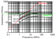
On the other hand, if you look at the datasheet I linked previously, you may decide that a 1L, 1R linear model might be adequate and sufficient for your needs. The Bourns FB73-226 might be an illustrative example (attachment).
You'll see that I drew a red line whose slope is 20dB per decade, which is the slope that perfect, ideal, linear inductors have; but that slope isn't a particularly good fit to the way the FB behaves. Ah the joys of modeling.
Attachments
Real ferrite beads are nonlinear. LTSPICE includes a (linearized?) model, whose component name is FerriteBead. I'll bet the Yahoo Groups LTSPICE website has got several additional ferrite bead models, which model the nonlinearities at several different levels of complexity.
On the other hand, if you look at the datasheet I linked previously, you may decide that a 1L, 1R linear model might be adequate and sufficient for your needs. The Bourns FB73-226 might be an illustrative example (attachment).
You'll see that I drew a red line whose slope is 20dB per decade, which is the slope that perfect, ideal, linear inductors have; but that slope isn't a particularly good fit to the way the FB behaves. Ah the joys of modeling.
Thanks a lot transistormarkj! 🙂 Saying 1L, 1R you mean to give equal values to each component of the model, am I right?
As for the ESR, do you think I ought to use the value derived from the worst dissipation factor, or the typical impedance at 100kHz?
For DCR (leakage resistance) I use 21,3k - since Imax=0.01CV, where Imax is leakage current, for the caps I want to use.
Well, after a bit of simulations, assumptions and evaluations, I have come to a conclusion I hope.
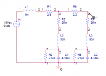
I decided to replace the first 2.2Ω resistor with a 1mH, 2.6Ω, 280mA inductor. I have found this one, but tomorrow I will check local availability for anything else.
This option is cheap: I would pay around 0.2 euro for each 5W resistor, now I will pay around 0.3 for each inductor. Which means negligible total extra cost. Also, such radial inductors will save me place in the final layout.
As for the frequency response, I simulated things a bit in Pspice. Assuming 25mΩ of ESR (quoted for 13mΩ, but why not add some more to include contact and trace resistances), 30nF of ESL (I think this is reasonable, and big if I refer to some articles I have read) and 213kΩ of leakage resistance - assuming 10% of maximum leakage current.
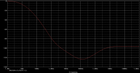
So, I attach the results. Given that the transformer winding will also introduce some leakage and resistance, the performance could be also "better". But, my main goal is achieved: adding around 80dB of attenuation for high frequencies (above 10kHz or whatever) to compensate for LM317's poorer rejection. To be more specific, to make sure I don't rely on it to reject high frequency garbage. 🙂
The performance is quite good, actually adding 80dB of attenuation above 1kHz - so even if in reality the performance becomes worse, I think it will be really good above 30kHz or so.
Next step, as Goatguy correctly suggests? Go buy stuff and try it in reality! 🙂
I decided to replace the first 2.2Ω resistor with a 1mH, 2.6Ω, 280mA inductor. I have found this one, but tomorrow I will check local availability for anything else.
This option is cheap: I would pay around 0.2 euro for each 5W resistor, now I will pay around 0.3 for each inductor. Which means negligible total extra cost. Also, such radial inductors will save me place in the final layout.
As for the frequency response, I simulated things a bit in Pspice. Assuming 25mΩ of ESR (quoted for 13mΩ, but why not add some more to include contact and trace resistances), 30nF of ESL (I think this is reasonable, and big if I refer to some articles I have read) and 213kΩ of leakage resistance - assuming 10% of maximum leakage current.
So, I attach the results. Given that the transformer winding will also introduce some leakage and resistance, the performance could be also "better". But, my main goal is achieved: adding around 80dB of attenuation for high frequencies (above 10kHz or whatever) to compensate for LM317's poorer rejection. To be more specific, to make sure I don't rely on it to reject high frequency garbage. 🙂
The performance is quite good, actually adding 80dB of attenuation above 1kHz - so even if in reality the performance becomes worse, I think it will be really good above 30kHz or so.
Next step, as Goatguy correctly suggests? Go buy stuff and try it in reality! 🙂
Attachments
Much better would be to use small gauge coax (stranded) cable for the power connections. The shield naturally is "ground". Works like a charm. The whole ferrite-bead thing seems like a whole lot of snake oil, when one considers the regulation and independence a 2-stage multi-regulator-output setup would deliver. But hey ... if you're going to use them, then make sure they're "transformer wound".
GoatGuy
For a power cable that is "floating" that is isolated from ground by a transformer, you can't ground the coax shield. That would defeat the isolation.
So I'd say coax cable is "out". What you need is shielded, twisted pair. This kind of cable is just what it sounds like the power is supplied via the twisted pair of conductors, the twisting cancels any kind of electric field. Then there is a braided cover of tinned copper over the pair. THis must be grounded to the power supply chassis AT ONE END ONLY. The other end MUST be left un connected. And then the power supply chassis is grounded to the wall outlet.
But do keep the negative power return floating from ground.
Ony ground ONE end of the shield, that is the only way to be 100% certain there is zero current in the shield.
Some people use the terms coax and shielded cable interchangeably but that is not correct. co-axial means the the axis of the wires are in the same place, very different from a shielded pair.
Here is a photo (but this is not the exact brand you need and #14 is to large for a 0.2A load)
http://ecx.images-amazon.com/images/I/213rWGS7d5L.jpg
Last edited:
I was planning to use such cable: two conductors to supply power, and one outer shield that is grounded at one end only.
Isn't that called coaxial cable too? I thought so. 😛 Thanks for the info!
I had a Belden type in mind, easily found locally. 🙂
Isn't that called coaxial cable too? I thought so. 😛 Thanks for the info!
I had a Belden type in mind, easily found locally. 🙂
Since the inductor is rated for only 0.28 amperes, the max power dissipated in the 2.2 ohm resistor "R6" is 0.28 x 0.28 x 2.2 = 0.173 watts. It doesn't need to be a 5 watt resistor. A 2.2 ohm 1/2 watt resistor (or two 1.1 ohm, 1/4 watt resistors in series) would do the job, with plenty of safety margin
Last edited:
A coaxial cable has:
Two conducting paths.
The central core.
The shield/return.
A twin-axial cable - aka: Shielded Twisted Pair (STP) has:
Three conducting paths.
Two central cores. (twisted)
The shield/return.
Two conducting paths.
The central core.
The shield/return.
A twin-axial cable - aka: Shielded Twisted Pair (STP) has:
Three conducting paths.
Two central cores. (twisted)
The shield/return.
Since the inductor is rated for only 0.28 amperes, the max power dissipated in the 2.2 ohm resistor "R6" is 0.28 x 0.28 x 2.2 = 0.173 watts. It doesn't need to be a 5 watt resistor. A 2.2 ohm 1/2 watt resistor (or two 1.1 ohm, 1/4 watt resistors in series) would do the job, with plenty of safety margin
Correct! Still, my layout provides me enough space to place a 5W. In general, they have less noise too - but this could be hardly an issue, anyway.
And today I bought a 1.2mH, 2Ω, 1.6A radial inductor for 0.09 euros. Yes, this is obviously my final choice. 😀
Speedskater, thanks for the comment!
Performing some simulations, I came up with something that seems a bit bad, concerning the direct use of an inductor after the bridge.
When I arranged the filter as L-C-R-C, I noticed some large spikes coming behind the inductor (behind = adjacent to the bridge). I assume that the large dI/dt ripple current that the first reservoir draws through that inductor, causes it to give a voltage spike.
So, the voltage waveforms in Pspice looked like the following:

The green waveform is the leg of the inductor that ties to the bridge - the spike is clear. After the inductance part follows the resistive part of the inductor (R11). The total voltage across it mimics the ripple current needed to charge the reservoir (red curve), while the voltage at the reservoir (purple curve) is the expected rectified voltage with a reasonable amount of ripple. The yellow curve is the input to LM317, that is the voltage waveform after smoothing caused by the cascaded R-C section.
So I thought a bit about what to do, and I decided to rearrange the filter making it R-C-L-C. The resulting waveforms:

So, everything looks smooth now. I believe that the solution lies in the fact that there is a much smaller ripple current through the inductor, so the spike phenomenon is eliminated. Seems to be the best solution, meaning nothing has to change except for the layout.
I would like to have a look at all these with the aid of an oscilloscope. I hope I will get the chance to monitor it in reality to see whether it really occurs. 🙂
The only "drawback"? The ac response of the total filter remains unchanged, except for the fact that above 10MHz, the attenuation goes from around -95dB to around -90dB. Hardly a concern, though. 🙂
When I arranged the filter as L-C-R-C, I noticed some large spikes coming behind the inductor (behind = adjacent to the bridge). I assume that the large dI/dt ripple current that the first reservoir draws through that inductor, causes it to give a voltage spike.
So, the voltage waveforms in Pspice looked like the following:
The green waveform is the leg of the inductor that ties to the bridge - the spike is clear. After the inductance part follows the resistive part of the inductor (R11). The total voltage across it mimics the ripple current needed to charge the reservoir (red curve), while the voltage at the reservoir (purple curve) is the expected rectified voltage with a reasonable amount of ripple. The yellow curve is the input to LM317, that is the voltage waveform after smoothing caused by the cascaded R-C section.
So I thought a bit about what to do, and I decided to rearrange the filter making it R-C-L-C. The resulting waveforms:
So, everything looks smooth now. I believe that the solution lies in the fact that there is a much smaller ripple current through the inductor, so the spike phenomenon is eliminated. Seems to be the best solution, meaning nothing has to change except for the layout.
I would like to have a look at all these with the aid of an oscilloscope. I hope I will get the chance to monitor it in reality to see whether it really occurs. 🙂
The only "drawback"? The ac response of the total filter remains unchanged, except for the fact that above 10MHz, the attenuation goes from around -95dB to around -90dB. Hardly a concern, though. 🙂
Last edited:
So I ordered a 100VA toroidal transformer with a 13.5VAC 5A winding to supply the requirements of the 10 9VDC power supplies needed. Went with Goatguy's approach.
Still, many members here (as I have read) insist on the fact that a single secondary feeding more than one bridges - power supplies etc, whatever, is problematic. I would like to know why, especially if someone has already had some experience with it.
And what could be considered to be better - 10 rectifier bridges after the winding, or one global bridge and 10 LM317's after? 😕
So I ordered a 100VA toroidal transformer with a 13.5VAC 5A winding to supply the requirements of the 10 9VDC power supplies needed. Went with Goatguy's approach.
Still, many members here (as I have read) insist on the fact that a single secondary feeding more than one bridges - power supplies etc, whatever, is problematic. I would like to know why, especially if someone has already had some experience with it.
And what could be considered to be better - 10 rectifier bridges after the winding, or one global bridge and 10 LM317's after? 😕
Simple answer: Ground loops. The number of rectifier bridges don't matter. the problem is the grounds are all tied together.
That said, maybe the ground lops are not so bad. But I don't see the point of going to all this hassle of independent regulators. Just go with one that can supply the entire load. Once you connect the ground it does not matter. Why not just buy a big 9V power cube. In fact that is just what you are building
You know you can buy a good supply with isolated grounds. Almost all the better power supplies you see in the guitar shop are isolated grounds.
Please audiostrat, do try to keep your eye on the simplicity of the situation.
[1] transformer: make sure there is a fuse in series with the primary and the power switch; it should be a "slow blow" type, of 1 amp.
[2] bridge rectifier: just use a 10 amp rated all-in-one bridge rectifier. They have PLENTY of "pulse current" capacity.
[3] wire in series to the bridge rectifier, a modest sized resistor - capable of dropping about 5 volts at 5 amps. That'd be a 1 ohm resistor [E = I R ; R = E / I ; R = 5/5 = 1.0!]
[4] then you have your first reservoir capacitor.
[5] then another series resistor ... again of 1.0 ohm.
[6] then another reservoir capacitor
THEN... "GoatGuy's recommendation":
[7a] six (6) to eight (8) LM7809 regulators on a heat sink... inputs tied together, outputs each independently attached to a 1uF buffering cap.
[7b] two (2) to three (3) LM317 regulators on separate heat sinks... inputs tied together, with the usual trim-pot to adjust output voltage.
[8] tie the outputs of all regulators to an interior screw-type terminal strip. This allows connection to the external-facing power cables that'll be plugged into EFX boxes. You want a terminal strip for MECHANICAL isolation of the cables from the regulators' fragile pins. (i.e. if one is tugged or pulled on, it won't break the interior wiring).
[9] mount all this on a tough board with a "heat-sink + protection box" on one side. This is where the transformer will go, along with all the regulators (mounted on the inside... as the heat-sink).
I don't think you need fuses for each regulator: they're already self-limiting in output current.
That's all!
GoatGuy
Simple answer: Ground loops. The number of rectifier bridges don't matter. the problem is the grounds are all tied together.
That said, maybe the ground lops are not so bad. But I don't see the point of going to all this hassle of independent regulators. Just go with one that can supply the entire load. Once you connect the ground it does not matter. Why not just buy a big 9V power cube. In fact that is just what you are building
You know you can buy a good supply with isolated grounds. Almost all the better power supplies you see in the guitar shop are isolated grounds.
I agree with you, I just want to gain experience through that build!
But all grounds will eventually be tied together. Imagine the fully isolated concept. Nothing goes to ground, everything floats.
After that, each 9VDC output (+ and -) goes to each pedal. There, it connect with the pedal's common point. And each common point for each pedal gets connected with each other through signal cables. All these tie to earth at the amp.
So, if I use 10 bridges, I can still implement that, since I will not connect all bridge grounds. They will be connected in the way I just analysed.
Am I missing something? Because I will not connect each ground with the others before they come to the box. This will happen anyway.
Are you referring to any other interference that can happen because the AC terminals of each bridge are common?
Sorry if I don't understand.
Please audiostrat, do try to keep your eye on the simplicity of the situation.
[1] transformer: make sure there is a fuse in series with the primary and the power switch; it should be a "slow blow" type, of 1 amp.
[2] bridge rectifier: just use a 10 amp rated all-in-one bridge rectifier. They have PLENTY of "pulse current" capacity.
[3] wire in series to the bridge rectifier, a modest sized resistor - capable of dropping about 5 volts at 5 amps. That'd be a 1 ohm resistor [E = I R ; R = E / I ; R = 5/5 = 1.0!]
[4] then you have your first reservoir capacitor.
[5] then another series resistor ... again of 1.0 ohm.
[6] then another reservoir capacitor
THEN... "GoatGuy's recommendation":
[7a] six (6) to eight (8) LM7809 regulators on a heat sink... inputs tied together, outputs each independently attached to a 1uF buffering cap.
[7b] two (2) to three (3) LM317 regulators on separate heat sinks... inputs tied together, with the usual trim-pot to adjust output voltage.
[8] tie the outputs of all regulators to an interior screw-type terminal strip. This allows connection to the external-facing power cables that'll be plugged into EFX boxes. You want a terminal strip for MECHANICAL isolation of the cables from the regulators' fragile pins. (i.e. if one is tugged or pulled on, it won't break the interior wiring).
[9] mount all this on a tough board with a "heat-sink + protection box" on one side. This is where the transformer will go, along with all the regulators (mounted on the inside... as the heat-sink).
I don't think you need fuses for each regulator: they're already self-limiting in output current.
That's all!
GoatGuy
If you see what I am doing, it goes well along with your logic! 🙂
I ordered the transformer. But I read that many bridges out of one winding, or the approach you suggest, can lead to problems because they prevent total isolation.
I am wondering about what problems could rise because someone uses only one winding. Have you ever had such problems?
What you say "isolation" what to you mean? I think you mean load isolation which hardly matters for something like this.
What you shoud care about is ground isolation. Here is a diagramhttp://http://www.premierguitar.com/Stream/StreamImage.aspx?Image_ID=749DABF1-BC9C-409B-A778-81FF68ED292E&Image_Type=image
The "rule" is that if you can trace a loop around a a grounded conductor you have a potential problem. OK, maybe the your loud guitar tone and the dummer completely blott out any small amount of hum and you don't care but the problem that using multiple regulators addresses is MUCH smaller then the ground loop problem.
It don't matter that all the ground eventually get back tied together. The problem is that current flows in the grounded conductor. It flows in the guitar cable and in the power cable. Both have grounded return paths that carry current. The cable has SOME (not much) resistance. By Ohm's law the voyage on each end of the grounded cable is different. The voltage on the end of the audi shield and power supply return will be different and curent will flow. You will have a "ground loop". Your signal (the music) is the deference between the signal voltage and the local ground reference. But your ground reference is moving and has noise on it. This noise adds to the music signal.
The way to avoid this is a "star ground" there is no way you can trace a circle on a star ground system.
Remember both Ohm's law and Kirchhoff's law and will make more sense. But the main thing people forget is the CURRENT actually flow in a grounded wire and you will then have a voltage gradient along the wire, even if it is small it must be present if there is current.
All that said, maybe a small about of hum does not matter, we are not taking about a lot, just the difference between decent and really good.
I understand all these, and I have considered them a lot.What you say "isolation" what to you mean? I think you mean load isolation which hardly matters for something like this.
What you shoud care about is ground isolation. Here is a diagramhttp://http://www.premierguitar.com/Stream/StreamImage.aspx?Image_ID=749DABF1-BC9C-409B-A778-81FF68ED292E&Image_Type=image
The "rule" is that if you can trace a loop around a a grounded conductor you have a potential problem. OK, maybe the your loud guitar tone and the dummer completely blott out any small amount of hum and you don't care but the problem that using multiple regulators addresses is MUCH smaller then the ground loop problem.
It don't matter that all the ground eventually get back tied together. The problem is that current flows in the grounded conductor. It flows in the guitar cable and in the power cable. Both have grounded return paths that carry current. The cable has SOME (not much) resistance. By Ohm's law the voyage on each end of the grounded cable is different. The voltage on the end of the audi shield and power supply return will be different and curent will flow. You will have a "ground loop". Your signal (the music) is the deference between the signal voltage and the local ground reference. But your ground reference is moving and has noise on it. This noise adds to the music signal.
The way to avoid this is a "star ground" there is no way you can trace a circle on a star ground system.
Remember both Ohm's law and Kirchhoff's law and will make more sense. But the main thing people forget is the CURRENT actually flow in a grounded wire and you will then have a voltage gradient along the wire, even if it is small it must be present if there is current.
All that said, maybe a small about of hum does not matter, we are not taking about a lot, just the difference between decent and really good.
What I don't understand, is why such problems could rise when using one secondary, and wouldn't when using separate ones. I will eventually connect all commons together in both cases. What is the difference then? 😕
A question for the final layout: does the arrangement of the secondary wires play an important role in hum issues, as far as the power supply alone is concerned?
I was initially thinking of twisting the wires until they reach the fuses, and then I would go again with twisted wire pairs to the rectifiers. But I suppose all this does not matter since all that filtering takes place afterwards, and we have no sensitive circuits nearby - eventually, all these currents will reach the rectifiers.
So, I have concluded that twisting wires could only help the guitar not to pick up any interference, and would add no significant noise to the whole power supply sytem. The box will be aluminum, so I am just a bit anxious about magnetic fields escaping it and reaching my pickups. 🙂
Do you agree with my opinions? I think I could also attach a thin sheet of steel below the top aluminum sheet, to shield things a bit from my guitar. Do you think this would help?
If you don't quite imagine the physical layout I am suggesting, please note it so I will elaborate a bit. 😉
So I decided to attach a quick sketch of the layout I am currently thinking, to clarify things a bit:

Of course, to simplify the sketch I just drew the wires for one supply only - same concept for each of them.
So I need your opinion on Option 1 vs Option 2:
(1) Do you think they have any difference as noise in the power supplies alone is concerned? (not the guitar coils)
(2) Will Option 2 prevent unwanted interference from reaching my guitar's coils?
(3) Do you think that just inserting a steel sheet (or something like that) as illustrated, would be better than using Option 2 in terms of shielding, thus making Option 2 useless?
Why asking all these? Just because I want to evaluate the lead lengths of each secondary to modify my order accordingly. 🙂
bigger loop area at your peril !
Sorry, but I don't understand what you mean! 😛
Are you referring to the wires not being twisted?
- Status
- Not open for further replies.
- Home
- Amplifiers
- Power Supplies
- Accurate voltage regulation