Also, if tuned correctly, it would give you the option to run the alpair by itself for some types of music if so inclined.Why would the full range need to be ported on top if crossing around 400Hz?
So - how do I guesstimate the port dimensions for the MLTL section? Or do I just go with whatever works on a simulation of a BR, since that's kind of the fall back outcome if I don't get any accidental MLTL effect?
Or am I better off seeing if I can ask nicely enough for someone to model it for me?
Or am I better off seeing if I can ask nicely enough for someone to model it for me?
GlenP,
I would use both 5in woofers in parallel and mount as if they weee a single driver with their mid point as location of the composite driver. This is to get you +6dB more bass sensitivity which is then neutralized by the -5dB baffle step loss on bass. Now overall system sensitivity is higher and equal to sensitivity of 1 driver and you won't have to pad your full range down. If 5in and full range are similar sensitivity it will all work out. On full range I recommend either sealed Dagger rear chamber, aperiodic vented TL (tapered short TL with lots of stuffing), or plain sealed but at 1/2Vas. This is to limit cone excursion and give open sound. Cross at 400Hz to 600Hz even. If using DSP try Harsch XO for realistic percussion.
Vent size as if BR.
GlenP,
I would use both 5in woofers in parallel and mount as if they weee a single driver with their mid point as location of the composite driver. This is to get you +6dB more bass sensitivity which is then neutralized by the -5dB baffle step loss on bass. Now overall system sensitivity is higher and equal to sensitivity of 1 driver and you won't have to pad your full range down. If 5in and full range are similar sensitivity it will all work out. On full range I recommend either sealed Dagger rear chamber, aperiodic vented TL (tapered short TL with lots of stuffing), or plain sealed but at 1/2Vas. This is to limit cone excursion and give open sound. Cross at 400Hz to 600Hz even. If using DSP try Harsch XO for realistic percussion.
Vent size as if BR.
Beauty - thanks a million.
You might consider joining this forum - Quarter Wavelength Loudspeaker Design. Someone may run sims for you.
Cheers Jimbro - have just done that. Being a designer (of other things, not speakers) I should have known better than to present any idea too soon, because it doesn't yet feel to me that I have quite arrived at the best that I can come up with. On the other hand the kindness of people here means that I have had valuable guidance and have been able to refine some thoughts before they got too far off the mark.
Finding someone to model it for me would be an excellent next step, so I've joined that group. Thank you.
Finding someone to model it for me would be an excellent next step, so I've joined that group. Thank you.
So you are looking for a sim of the MLTL portion of your multiway speaker? I can run a basic straight MTL of about 45in long path and see where that ends up at. Do you have TS parameters - please post and give me a few days.
So you are looking for a sim of the MLTL portion of your multiway speaker? I can run a basic straight MTL of about 45in long path and see where that ends up at. Do you have TS parameters - please post and give me a few days.
That would be awesome. Thanks so much.
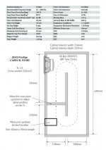
I've changed my design quite a bit - I'm attaching a picture. I've found the 5" SEAS driver, which I like and it seems to model really well in the size I want. This translates to the TL having a cross section of about 3xSd. The volume and port length are pretty good, according to the online calculator I used. Sensitivity is not a problem because I am going to do active.
The total height from end to end twice is about 47", but I am not sure what account I am supposed to make of the "going around the bends bits", so 45" might be more like it? Hopefully my drawing is clear.
Thanks again.
Glen
Attachments
Ah - just thought, you might prefer the drawing in inches? Just say if you do and I'll convert it.
This is fine, and I get roughly 49in length. The turns assume two segment to the 45 degree diagonal. For a 90 degree square turn the lengths work out as if the length of the turn is same as the width.
Havent had a chance to look at response but thought this driver might make an interesting mini mltl candidate. Basically a high output 5" sub with good sensitivity. I imagine it cd be used as a mid bass crossed low
Peerless SLS-P830945
Peerless SLS-P830945 5-1/4" Paper Cone Woofer 4 Ohm
Peerless SLS-P830945
Peerless SLS-P830945 5-1/4" Paper Cone Woofer 4 Ohm
That's a nice driver, Bill Poster. Haven't seen it before as it is new - good specs and nice price. The Qts is actually on lower side and perfect for bass reflex but might not be easiest to use for a AMLTL - as tuning frequency below Fs will be tough to achieve.
Thanks,
X
Thanks,
X
The little SEAS I found stacks-up quite nicely I think. The Sd is 104 cm2 and the Qts is 0.45, VAS 19 litres. With the packaging that I want, which is basically a 250mm wide 650mm high 350mm deep box to go under a full range top section (comes out at about 40 litres, roughly) it gets a good BR tune with enough volume to play with to create a variety of TL shapes. The design I sketched eventually is quite neat and has a constant x-section of around 3xSd with quite a long line length.
I followed advice and joined the Quarter Wave Group, and Martin took a look and said "…it looks like a pretty good design. Bass down to about 30 Hz and a flat SPL response with 0.25 lb/ft^3 of stuffing."
I like the look of the metal driver and the size is cute and I think it will go well with an Alpair metal top section. I'm going to do active, so the low-ish sensivity isn't too much of a problem (Class-D watts are good value). Against a wall and with a A7.3 top section you could maybe do passive?
I'm only a beginner but I'm happy that I've got my head around the basic requirements, plus I've come up with a nice simple cabinet with bracing built-in. The driver can go near the top, because the line termination can be set by where you put the cross-piece, meaning that you design for optimum driver offset even though the driver is at the top of the cabinet. This puts lots of room directly behind the driver too.
No doubt it would be possible to go louder and lower with the same cabinet dimensions and a standard BR with a larger driver (8" would fit), but this design gets me as loud as I'm going to need with a modestly priced driver that I think looks right.
I have been convinced now of the value of doing a proper modelling and intend seeing if I can get the old Windows laptop that is in the roof going, so that I can try and learn the software.
I realise now that this is way too much detail for the topic of this thread - suffice to say that I think I get the desired relationship between Sd, VAS, cabinet volume and Qt. Qt on the high side for BR, basically!
Hi GlenP,
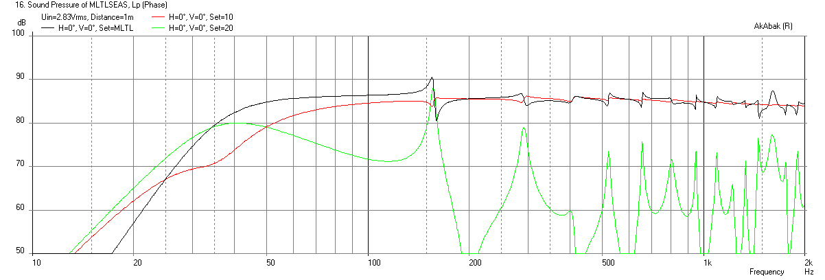
I put in the TS params that you provided for the SEAS driver and not sure if something is off but I get a rather low sensitivity of only 72dB at 2.93v. In any event, using the dimensions you provide below, I get a decent looking response with an F3 of 37Hz. So the design should sound decent assuming everything else about the TS parameters is good except the sensitivity. Here is the predicted response. Of course it won't go above the real stated breakup limit as the sim assumes a perfect piston diaphragm.
Cheers,
X
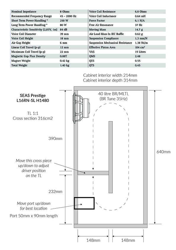
Here are TS params I used:
SPL at 2.83v and 1m (port assumed to be 4in from end, driver assume to be 17in from sealed end):
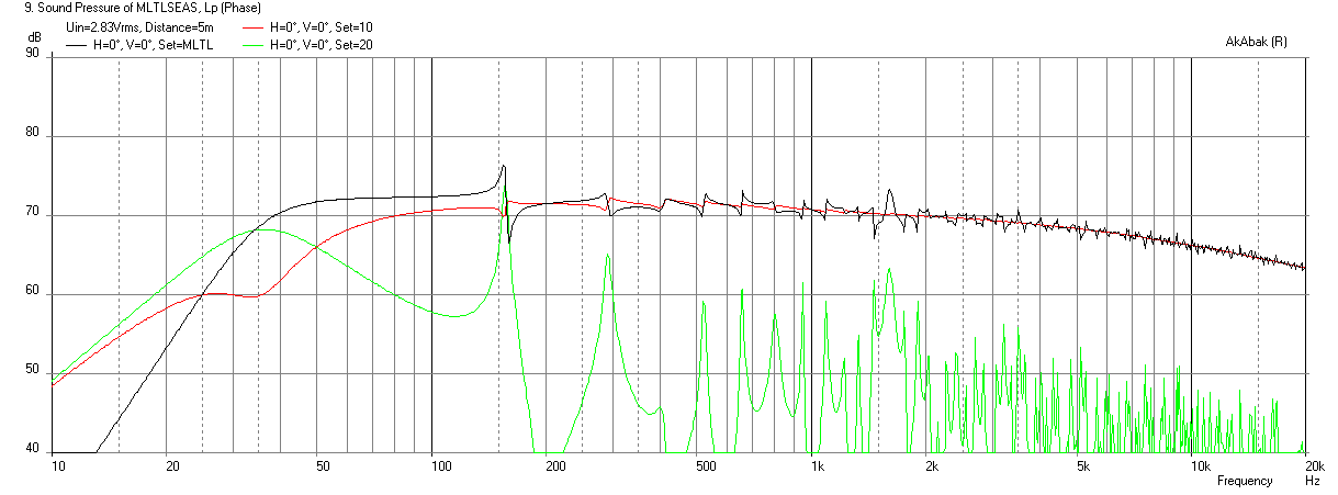
I put in the TS params that you provided for the SEAS driver and not sure if something is off but I get a rather low sensitivity of only 72dB at 2.93v. In any event, using the dimensions you provide below, I get a decent looking response with an F3 of 37Hz. So the design should sound decent assuming everything else about the TS parameters is good except the sensitivity. Here is the predicted response. Of course it won't go above the real stated breakup limit as the sim assumes a perfect piston diaphragm.
Cheers,
X
Here are TS params I used:
Def_Driver 'SeasL16RN' | 84dB 6mm xmax, Qts 0.45 80w
SD=104cm2 |Piston
fs=37Hz
Vas=19L
Qms=2.48
Qes=0.55
Mms=14.7g
Re=6.0ohm
Le=0.64mH
SPL at 2.83v and 1m (port assumed to be 4in from end, driver assume to be 17in from sealed end):
Attachments

That's strange, because the regular BR calculator gave me 84.29 DB/W/M and an F3 of 34Hz just in a regular 40 litre box.
Something isn't correct then. I notice that if I put in the VAS as 1.9, rather than 19 then the sensitivity goes down to 74.29 DB/W/M.
Thanks very much for taking the time and showing interest by the way.
Glen
Something isn't correct then. I notice that if I put in the VAS as 1.9, rather than 19 then the sensitivity goes down to 74.29 DB/W/M.
Thanks very much for taking the time and showing interest by the way.
Glen
Ah - so obvious after one's seen it! I thought perhaps it was some sort of decimal place error.
As a more general question; this simulation (thanks, once again) doesn't have any greater extension than the conventional BR calculator gives - the F3 of the normal calculation is 34Hz. Does this indicate that this particular cabinet design isn't really doing anything (at any rate, not the thing that I was hoping for)? Or is it the case that a mltl design might produce different sound characteristics, even if deeper extension isn't one of them?
As a more general question; this simulation (thanks, once again) doesn't have any greater extension than the conventional BR calculator gives - the F3 of the normal calculation is 34Hz. Does this indicate that this particular cabinet design isn't really doing anything (at any rate, not the thing that I was hoping for)? Or is it the case that a mltl design might produce different sound characteristics, even if deeper extension isn't one of them?
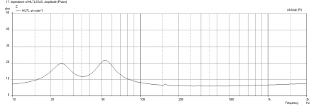
You can get deeper extension at the expense of reduced SPL. A MLTL has an altogether better sound for the bass - not boomy - very articulate and clean. Also, the impedance will be flattened out somewhat rather than two sharp peaks as you would get with a BR. The smoothing is mostly due to damping and can be adjusted. The smoother impedance curve will sound better as the amp can deliver more current throughiyt the bass region without having two high impedance peaks to cross through. This gives punchier, more accurate bass.

Here is cone excursion at xmax of 6mm (13vrms drive) with -12dB/oct HPF at 35Hz to prevent infrasonic over-excursion. If you don't have content down there it is not a concern:
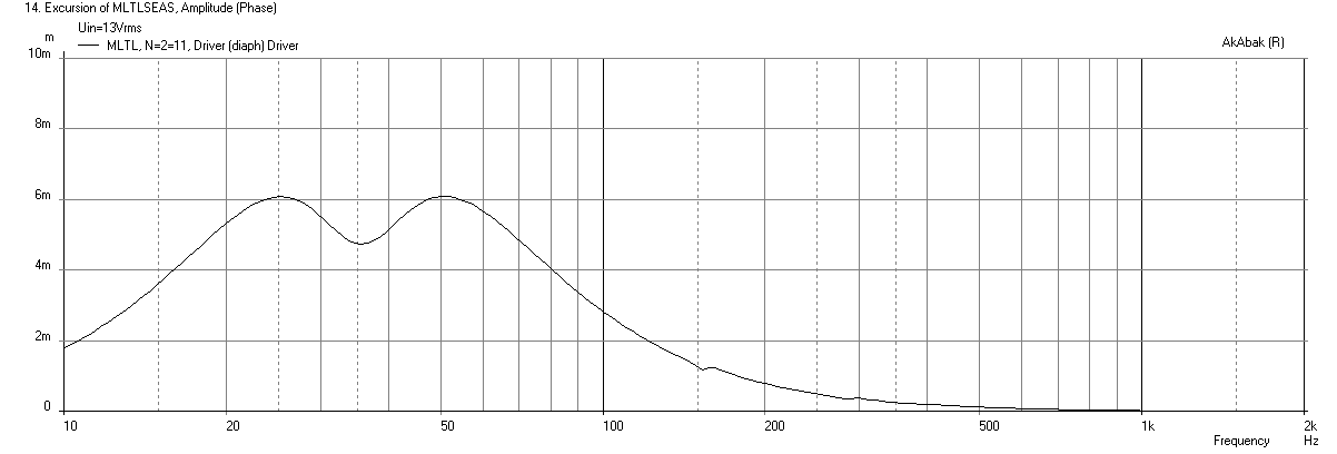
Here is corresponding max SPL - it's only 100dB and that is kind of low and probably due to fact that design has such a large volume, excursion is not as well controlled as a smaller volume box (of same volume as Vas). Such a box made with an XKi for example, will have same extension but higher SPL due to better cone control.
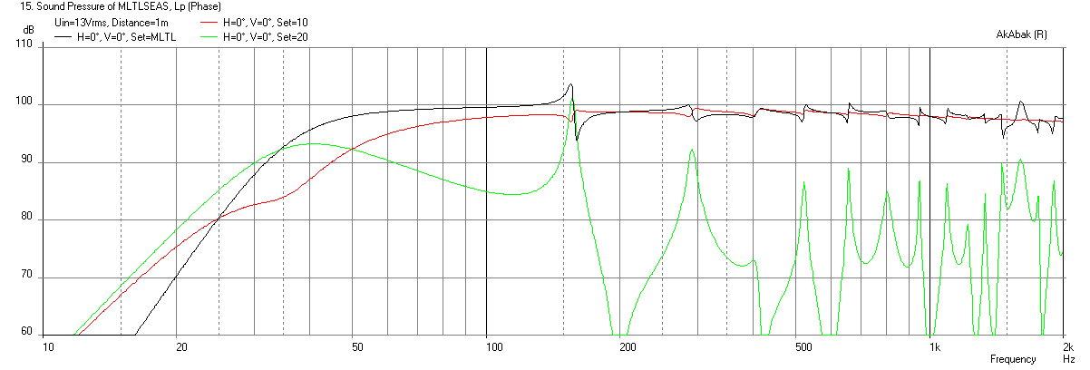
For completeness, here is response at 2.83v/1m:
Here is cone excursion at xmax of 6mm (13vrms drive) with -12dB/oct HPF at 35Hz to prevent infrasonic over-excursion. If you don't have content down there it is not a concern:
Here is corresponding max SPL - it's only 100dB and that is kind of low and probably due to fact that design has such a large volume, excursion is not as well controlled as a smaller volume box (of same volume as Vas). Such a box made with an XKi for example, will have same extension but higher SPL due to better cone control.
For completeness, here is response at 2.83v/1m:
Attachments

Last edited:
It remains a puzzle for me how to have the large volume necessary for an adequate cross section, combined with a small enough volume for the cone control you mention. I guess there may well be better drivers for these enclosure dimensions. Or maybe I ought to make it a bit less tall with a smaller volume and shorter TL.
The target keeps moving (something which appeals to my restless mind!) as I get more things figured out I move on to other refinements/options. When I have got some competence with simulation software I will experiment with a larger driver and a tapering TL, and also with this driver but with reduced volume.
Having said all of the above, max SPL of 100DB is more than Alpair 7.3 will do anyway, and only a little shy of what an A10.3 can manage safely - and way below the likely level in my lounge! Also, I don't for a second doubt the sophistication of XKi, but simplicity of build is a very high priority for me and a rectangular box with perpendicular two braces and no angled cuts is quite an elegant solution in my mind.
- Home
- Loudspeakers
- Full Range
- Accidental MLTL Technique