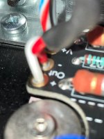
@6sX7: Thank you; that is what I was going to use but I saw the photo and was baffled. I thought it was an integrated item but birdbox made the AHA moment when he said it was an ordinary hex head cap bolt. Thank you to birdbix too!

one channel is cooking. There was some magic smoke that escaped in the process. Will bias the other then get the input wiring finished and make sure I didn't permacook something in the right channel.

Left channel is now cooking. Zero magic smoke escaped. I got rambunctious with the right channel, not paying attention to the biasing. At one point, Vb read 1.4V. That's when I started thinking about some nice peaty Scotch while frantically turning pots down.
exactly. Scotch should be smoky, amps not so much.
One done. finally. Makes the 2nd easy as I know how to wire it up now.
Works in SE and Balanced mode. I skipped the parallel switch. Will try it at a later date. Wasn't sure how it would like things if balanced was hooked up and I accidently hit the switch. Theoretically, should hear silence as halves cancel, yes?
Doesn't sound like any lasting damage occurred from over-biasing it for the moment it happened. Reading up on how to do some basic testing. But first, the 2nd unit!
Last edited:
Wasn't sure how it would like things if balanced was hooked up and I accidently hit the switch. Theoretically, should hear silence as halves cancel, yes?
Yes, a balanced signal would cancel. Shorting XLR pins 2 and 3 is how the mute switch functions in some pro-audio gear like microphones or, for example, this XLR connector, and a project from ESP. I wouldn't expect and issues but there could still be a pop / thump so best to test it with less than precious speakers in case your source behaves differently than mine.
2nd unit is up and running. Had another "oh-no" moment. Forgot to turn down the pots on the right channel. SMPS went into protect mode when I turned it on. Realized immediately. Cranked down the pots and the LEDs stopped pulsing. Otherwise, biased up just fine. Now I need to get a 2nd PSU so I can actually listen to them in balanced mode.
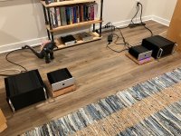
Attachments
Have the 2nd PSU now. One amp is louder than the other. Time to put them back on the bench and start troubleshooting.
Put them up on the o-scope with a 1kHz sine wave supplied to ChA of each one from my Macbook Pro. Got sine wave on top of sine wave. Did Ch1-Ch2 and had white noise. I'm new to O-scopes so I think I'm hooking it all up correctly but not certain of myself.
I put them back in the system, left side sounded louder. Swapped amps and I think it has followed. Unsure if I'm just hearing things. Will look at R5s and R6s tomorrow.
I put them back in the system, left side sounded louder. Swapped amps and I think it has followed. Unsure if I'm just hearing things. Will look at R5s and R6s tomorrow.
I'm also wondering if I'm having tracking issues in the DAC volume pot. The MinMaxes have more gain than the F4s. I haven't adjust the output jumpers accordingly and having to turn the pot almost all the way down.
Put a 1kHz tone on both of them while in the stereo. Comes up dead center. I am "hearing" things apparently.
I applaud your skepticism and bravery! Congratulations to member @6sX7 for daring to imagine that a perception might possibly be incorrect. Good on ya.
Speaking of skepticism and bravery, attempting to measure the max output of one of these MinMaxes running balanced. I believe I have it hooked up correctly (via an afternoon visit with @6L6 that resulted in a phone call to the one and only @Mark Johnson):
O-scope Channel 1 is on + output of Channel A.
Ground clip is on - output of Channel A.
O-scope Channel 2 is on + output of Channel B.
Subtracted Ch2 from Ch1 via the built-in math function.
Input is a 1kHz tone from the balanced output of my Benchmark DAC3
Output is hooked up to a 300W 8R dummy load
Pictures attached. Waveform on the O-scope is right before the sine wave started flattening ( was very excited to see it flatten out). Reading thru the manual to find out how to interpret the scale.
Fluke DMM read 19.45Vac.
The dummy load got warm, the amp heatsinks cooled down. Was way cool to see this all at work and jive with what the engineering/physics says it should do. Once I figure out the scale, can compute P=V^2/R.


I am a kid again.
O-scope Channel 1 is on + output of Channel A.
Ground clip is on - output of Channel A.
O-scope Channel 2 is on + output of Channel B.
Subtracted Ch2 from Ch1 via the built-in math function.
Input is a 1kHz tone from the balanced output of my Benchmark DAC3
Output is hooked up to a 300W 8R dummy load
Pictures attached. Waveform on the O-scope is right before the sine wave started flattening ( was very excited to see it flatten out). Reading thru the manual to find out how to interpret the scale.
Fluke DMM read 19.45Vac.
The dummy load got warm, the amp heatsinks cooled down. Was way cool to see this all at work and jive with what the engineering/physics says it should do. Once I figure out the scale, can compute P=V^2/R.
I am a kid again.
ok, I think I found a measurement setup mistake. I believe I ignorantly set the probe attenuations to 100x. If I understand correctly, the demarcations are then 10V ea. So peak to peak is roughly +/-28V. RMS is 19.6 which is what the DMM told me. Rounding up to 20V rms P = 20^2/8 = 50W. I'll have to try measuring again tomorrow. In the meantime, seem reasonable?
brain churning. my Kill-a-watt is reading about a 45W draw at the outlet. So, the 50W output can't be. Silly perpetual motion machine. Retry measurements tomorrow with a fresh brain and time to read the o-scope manual.
I'm a little savvier on this O-scope. I looked at the output of each channel given a 1kHz input.
Channel A of the suspect amp has something going on with it. Otherwise, all other channels measured 1.62V p-p output given a 300mV p-p 1kHz input.
Picture of Suspect Channel A output below. It biased up fine. Some more troubleshooting later this week. Input waveform changes when I hook up to the probe to the output channel. Maybe a short somewhere.
Last edited:
ok. learned a bit more on how to use the o-scope.
1st picture here is the left channel. There is some asymmetry between the L & R channels in the amp. Going to poke at that more later.
Vp-p = 26.4V
Vrms = 0.7071*Vp-p = 18.7Vrms
P = Vrms^2/R = 18.7^2/8 = 44W

2nd picture is the right channel. Internal L & R channels very symmetric.
28.8Vp-p.
Vrms = 20.4Vrms
Prms = 20.4V^2/8 = 52W.

I half-figured out the puzzlement with the Kill-A-Watt. "Watt" mode is "active" power. "VA" mode is the "apparent" power. "Apparent" power is Vrms * Arms. Not sure what "active" power is. Anyways, in "VA" mode, it's showing 90W which seems logical given class A operation, the measured output of the amps and the Kill-A-Watt is reading ~0.7A.
So, ya. Getting a good 50W out of these little amps in balanced mode. Heatsinks are sitting around 45C.
1st picture here is the left channel. There is some asymmetry between the L & R channels in the amp. Going to poke at that more later.
Vp-p = 26.4V
Vrms = 0.7071*Vp-p = 18.7Vrms
P = Vrms^2/R = 18.7^2/8 = 44W
2nd picture is the right channel. Internal L & R channels very symmetric.
28.8Vp-p.
Vrms = 20.4Vrms
Prms = 20.4V^2/8 = 52W.
I half-figured out the puzzlement with the Kill-A-Watt. "Watt" mode is "active" power. "VA" mode is the "apparent" power. "Apparent" power is Vrms * Arms. Not sure what "active" power is. Anyways, in "VA" mode, it's showing 90W which seems logical given class A operation, the measured output of the amps and the Kill-A-Watt is reading ~0.7A.
So, ya. Getting a good 50W out of these little amps in balanced mode. Heatsinks are sitting around 45C.
Last edited:
- Home
- Amplifiers
- Pass Labs
- ACA MinMax - ACA mini retrofit for ACA chassis