FYI - It's a good thing that the solder "wicks" thru to the other side, means you had sufficient heat and penetration in the joint. Make sure your soldering iron is hot enough 325-400C (I use 375-400 personnally) and make sure you touch the pad AND the lead both at the same time, you should see the solder melt and "flow" into the joint, leave iron on joint for 1-2 secs and lift iron away.
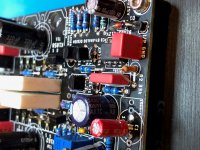
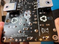
Couple example top/bottom pics for reference.
Couple example top/bottom pics for reference.
Attachments
I suspect that your issue lies in the solder joints. What solder are you using? I use Cardas which is like soldering with butter. your suspect solder joints look a little cold.
Regarding my post above, the sleeve is the outside conductor of the RCA jack on a male end. I was saying to check from the source side of the cable that goes to the amplifier to the negative binding post on the amplifier. Of coarse with the RCA cable connected. This just confirms that both the cable, the RCA jack and the solder connection at those points are good to go. The RCA ground and the negative terminal share the same solder trace on the board.
Reflow the solder joints and report back. 🙂
I don't think this has anything to do with solder joints. If nothing else all this random heating and reheating of components can only introduce new issues like fried components and traces.
I'd suggest to put the soldering iron down and start by measuring with an ohm meter. See if you spot differences between the side that works and the one that doesn't. Most of these supposed cold joints should be testable.
I'd suggest to put the soldering iron down and start by measuring with an ohm meter. See if you spot differences between the side that works and the one that doesn't. Most of these supposed cold joints should be testable.
The heatsinks connected to the ground? I dont remember that on my boards! Strange!
Did you isolate the Q3 and Q4 between the body and the heatsinks?
The heatsinks connected to the ground? I dont remember that on my boards! Strange!
Did you isolate the Q3 and Q4 between the body and the heatsinks?
Are Q1 & Q2 on the right hand side of the board in backwards?
I’ll post closer pictures. They look oriented correctly, and I don’t think the heat sink is in the ground. I started testing the resistors. They look the same on both sides. I also tested everything before mounting on the board. I’m at a loss.Are Q1 & Q2 on the right hand side of the board in backwards?
I double checked the mosfets and 520 in Q4 and 9520 in Q3. I didn’t use thermal paste because I don’t have any.
No. Starts when red RCA is plugged in. When powering up with both speakers connected and just one RCA connected to the green side, plays fine from that side. Problems start when connected to the red RCA input.does it make the buzzing sound when nothing is plugged into the input?
The guide mentioned using a heatsink goop if you have some. However, you can take your finger and put it on the MOSFET. If it is significantly hotter than the heatsink then the interface between the two needs to be improved. A good thermally conducting interface should only be up to 5 degrees Celcius difference.
Confirm that the outer connection of the RCA on the ACA is making a good closed connection with the negative binding post using your multimeter
Confirm that the outer connection of the RCA on the ACA is making a good closed connection with the negative binding post using your multimeter
Like I said, start testing for differences between the side that works and the side that doesn't with a simple ohmeter without power. You will get some hints. Alternatively, under power, hookup an 8 ohm 10W resistor as load and test voltages on each channels so that the buzz doesn't bother you.No. Starts when red RCA is plugged in. When powering up with both speakers connected and just one RCA connected to the green side, plays fine from that side. Problems start when connected to the red RCA input.
Don't worry about paste on the mosfet. That's not the issue.
Hi. Just finished the ACA mini build and biased it last night. Tested it with Schiit SYS and cd player and sounded good. Today, I moved some things around to make room for all the stuff, and one of the speaker wires came loose. Reconnected and now, when I fire the thing up, loud feedback/buzz/noise from one side (red). Any ideas what I should check appreciated.
So at one point it was working, then it stopped. Does it still make sound together with the buzz or it's just buzz? If it's just buzz then damage to semi may have occurred.
Are all the components (CD player, turntable, amplifier, etc…) all plugged into the same outlet and/or power strip in that same outlet? I’m wondering if this may be a ground loop through the AC earth…
Thanks. Not sure what “hookup an 8 ohm 10w resistor means”. I’m an ignorant amateur tying to learn skills.Like I said, start testing for differences between the side that works and the side that doesn't with a simple ohmeter without power. You will get some hints. Alternatively, under power, hookup an 8 ohm 10W resistor as load and test voltages on each channels so that the buzz doesn't bother you.
Don't worry about paste on the mosfet. That's not the issue.
- Home
- Amplifiers
- Pass Labs
- ACA Mini loud buzz/hum