No needed for Transistor changes with 24v, just simple drop in.Thanks. So at 24V are the Q1/Q2 pairs: FQH44N10/FQH44N10 or FQH44N10/ IRFP140 just considered simple drop-in replacements? Or are there resistor changes too necessary? Reading though the forum it is difficult to determine if any adjustments are necessary for Q1/Q2 changes when running at 24V. For 36V it is clear changes are required.
I would love to work with some folks on a nice dual mono linear power supply for the 36v ACA, maybe we could do a version for 24v.
Coming up with a BoM, chassis, it'd be great to work on one together on a thread.
Coming up with a BoM, chassis, it'd be great to work on one together on a thread.

YES!!!! Can you share some wisdom on this one, I would love to be able to put this together! are these the Smooth Like Butter boards?
Yes, those are a pair of single rail SLB boards.
The description of the PSU build starts here:
Post in thread 'DIY Sony VFET Builders thread'
https://www.diyaudio.com/community/threads/diy-sony-vfet-builders-thread.370689/post-6685621
I added 30,000 uF of capacitance per channel inside the VFET amp chassis. I would suggest something similar with the ACA.
Oh awesome, thanks I will start digging into that thread!Yes, those are a pair of single rail SLB boards.
The description of the PSU build starts here:
Post in thread 'DIY Sony VFET Builders thread'
https://www.diyaudio.com/community/threads/diy-sony-vfet-builders-thread.370689/post-6685621
I added 30,000 uF of capacitance per channel inside the VFET amp chassis. I would suggest something similar with the ACA.
Could there be a 24V version too? I wasn't wanting to tackle something like that, but it looks so cool, I'd like to build one.Oh awesome, thanks I will start digging into that thread!
I built a double dual rail for 2× +/-24v. Used the CRC cap bank pcb from Randy Thatcher (but it works with every other) and a little board for the inrush current limiter. The donuts are 2x115vac/2x18vac 300va.Could there be a 24V version too? I wasn't wanting to tackle something like that, but it looks so cool, I'd like to build one.
VEEERY NICE👍That is beautiful work. Well done!
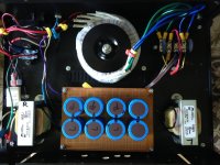
the linear power for my ACA....It puts out two 35 volt lines on a 3 conductor power cord that I adapted to plug into the IEC plug on the back of the case that houses the ACA. Under load it drops to 26.7 volts for each channel. I never had any hum problems with the kit power brick, but I never did get all of the hum out of the linear power supply until I built it in a separate enclosure. Without the separate power supply case, it was too cramped and I needed the extra room for more storage capacity. The main capacitor banks are inside the amp case, the former house of an old B&K St-140 amp. The power supply lives inside the former case of a Superphon amp.VEEERY NICE👍
Attachments
Thank you both! 
Looks great! Is it a CLC? My goal was to keep the (possible) hum-source outside of the amp, and of course the (planned) amount of the amps 🙂 In the PSU I have 132mF per rail and the amps will get 33mF per rail per channel.the linear power for my ACA....It puts out two 35 volt lines on a 3 conductor power cord that I adapted to plug into the IEC plug on the back of the case that houses the ACA. Under load it drops to 26.7 volts for each channel. I never had any hum problems with the kit power brick, but I never did get all of the hum out of the linear power supply until I built it in a separate enclosure. Without the separate power supply case, it was too cramped and I needed the extra room for more storage capacity. The main capacitor banks are inside the amp case, the former house of an old B&K St-140 amp. The power supply lives inside the former case of a Superphon amp.
I have to say my ACA built with the Universal Power Supply (60,000 µF) in a Deluxe 4U case that I first used to build an F4 is a keeper. I had a rack of IRFP150M's so I used those. It's been 10 months and I have no desire to change anything. Love it!
It is CLC. There is 27,200 per channel in the power supply, and 66,000 more per channel in the case with the amp.Thank you both!
Looks great! Is it a CLC? My goal was to keep the (possible) hum-source outside of the amp, and of course the (planned) amount of the amps 🙂 In the PSU I have 132mF per rail and the amps will get 33mF per rail per channel.
Looking for a quality replacement part for C3 (Elna 10uF 25V) - It is now end of life component.
I hope to get my parts from Mouser.
Any ideas?
I hope to get my parts from Mouser.
Any ideas?
Mouser No: 555-RFS25V100MF3#5 Manufacturers No: RFS-25V100MF3#5 |
just buy any brand name, declared as "for Audio"
at least 50% of chance to get part, not BS
if you worry, just bypass it with 100n-1uF solid cap and you have it
solid cap of my choice is polycarbonate; if nothing else, name sounds more fancy to me than other sorts of plasticky names
at least 50% of chance to get part, not BS
if you worry, just bypass it with 100n-1uF solid cap and you have it
solid cap of my choice is polycarbonate; if nothing else, name sounds more fancy to me than other sorts of plasticky names
Yes, there are many good options for C3 in the ACA. It doesn't have to be 10uF. Since the ACA has a high input impedance, even a 0.47 uF to 1.0 uF film can do just fine. I also like polycarbonate, though they are more difficult to find these days. Some other good ones are the Wima red box polypropylene, as Nelson uses in the recent VFET amps.
Just to be sure, would this be ok?
Mouser No: 505-MKP2D034701M00KS
Mfr. No: MKP2D034701M00KSSD
Or can you give better option which is available?
Wima Polypropylene (PP) Film Capacitors MKP 2 0.47 uF 100 VDC 8.5x14x7.2 PCM 5 |
Mouser No: 505-MKP2D034701M00KS
Mfr. No: MKP2D034701M00KSSD
Or can you give better option which is available?
I want to contribute my findings.
I have completed the ACA v1.8 build with the mods as suggested by TungstenAudio and Zamjazz27.
The build changes from stock:
===========================
C1: 4700 uF, 35V; Nichicon KG series "Gold Tune" (output capacitor)
C2: 1000 uF, 16V; Nichicon RNL series Aluminum Organic Polymer
C4: 100 uF, 35V; Nichicon RL8 series Aluminum Organic Polymer (power rail bypass)
R3: 0.56Ω 3W 2% metal oxide or film resistors (R3 &R4 changes request reset to bias voltage to 12.4v)
R4: 0.56Ω 3W 2% metal oxide or film resistors (R3 &R4 changes request reset to bias voltage to 12.4v)
R11: 20 kOhm, 1/4W, 1% metal film (Input Resistor), stock was 10k
R12: 90.9 kOhm, 1/4W, 1% metal film (Feedback Resistor), stock was 39.2k
Q1/Q2: FQH44N10 - at 24v just a drop in replacement
68.1 kOhm Bridging Resistor: 1/4W, 1% metal film. bridge Resistor (R16) to replace the stock 39k (If one has a modified ACA with 20k for R11 and 90.9k for R12, then the bridging resistor needs to be 68k in order to balance the levels of the two boards. the 68.1k resistor is only for bridge mono)
C101: 10 pF, 500V, 5% Silver Mica; added in parallel w/ R12 - First choice would be film (polypropylene or polystyrene)
, second choice silver mica. Avoid ceramic, even NPO/C0G could have adverse sonics.
===========================
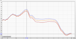
After the completed build I performed various listening tests cycling through the different connection options (stereo/Mono XLR Bridged/Mono RCA Bridged/Mono RCA Parallel).
What I noticed could be described as a sibilance. I spent several hours cycling through the connection options and always with some options it was an unmistakable sibilance (esses). So I broke out Room EQ Wizard and took measurements of each connection option. Each measurement consisted of exactly the same speakers, exact same location for speakers and mic, exact same cables/wire except for RCA vs. XLR of course, and I found the following:
These are the frequency responses of 'my' speakers (GR Research LGK 2.0) in 'my' room, but with that said, a pattern emerged (see frequency response chart).
At 9kHZ and below the connection options all produced the exact same frequency response. But starting at 9kHZ and above there became a divergence in the frequency response.
The Red line is the XLR/RCA Bridge Mono connection option.
The Gold line is the Stereo connection option, more sibilant than XLR/RCA Bridge Mono.
The Blue line is the Bridged Parallel connection option, more sibilant than Stereo and even more sibilant than XLR/RCA Bridge Mono.
At its worst there was a ~2dB difference in the 13kHZ - 16kHZ range.
Thoughts as to why that could be?
I have completed the ACA v1.8 build with the mods as suggested by TungstenAudio and Zamjazz27.
The build changes from stock:
===========================
C1: 4700 uF, 35V; Nichicon KG series "Gold Tune" (output capacitor)
C2: 1000 uF, 16V; Nichicon RNL series Aluminum Organic Polymer
C4: 100 uF, 35V; Nichicon RL8 series Aluminum Organic Polymer (power rail bypass)
R3: 0.56Ω 3W 2% metal oxide or film resistors (R3 &R4 changes request reset to bias voltage to 12.4v)
R4: 0.56Ω 3W 2% metal oxide or film resistors (R3 &R4 changes request reset to bias voltage to 12.4v)
R11: 20 kOhm, 1/4W, 1% metal film (Input Resistor), stock was 10k
R12: 90.9 kOhm, 1/4W, 1% metal film (Feedback Resistor), stock was 39.2k
Q1/Q2: FQH44N10 - at 24v just a drop in replacement
68.1 kOhm Bridging Resistor: 1/4W, 1% metal film. bridge Resistor (R16) to replace the stock 39k (If one has a modified ACA with 20k for R11 and 90.9k for R12, then the bridging resistor needs to be 68k in order to balance the levels of the two boards. the 68.1k resistor is only for bridge mono)
C101: 10 pF, 500V, 5% Silver Mica; added in parallel w/ R12 - First choice would be film (polypropylene or polystyrene)
, second choice silver mica. Avoid ceramic, even NPO/C0G could have adverse sonics.
===========================
After the completed build I performed various listening tests cycling through the different connection options (stereo/Mono XLR Bridged/Mono RCA Bridged/Mono RCA Parallel).
What I noticed could be described as a sibilance. I spent several hours cycling through the connection options and always with some options it was an unmistakable sibilance (esses). So I broke out Room EQ Wizard and took measurements of each connection option. Each measurement consisted of exactly the same speakers, exact same location for speakers and mic, exact same cables/wire except for RCA vs. XLR of course, and I found the following:
These are the frequency responses of 'my' speakers (GR Research LGK 2.0) in 'my' room, but with that said, a pattern emerged (see frequency response chart).
At 9kHZ and below the connection options all produced the exact same frequency response. But starting at 9kHZ and above there became a divergence in the frequency response.
The Red line is the XLR/RCA Bridge Mono connection option.
The Gold line is the Stereo connection option, more sibilant than XLR/RCA Bridge Mono.
The Blue line is the Bridged Parallel connection option, more sibilant than Stereo and even more sibilant than XLR/RCA Bridge Mono.
At its worst there was a ~2dB difference in the 13kHZ - 16kHZ range.
Thoughts as to why that could be?
Attachments
- Home
- Amplifiers
- Pass Labs
- ACA amp with premium parts