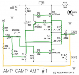
Since R12 is the feedback resistor, it counts as being in the signal path.
As a matter of naming, I use the R16 designation for an extra resistor placed between the (+24V) power rail and C4. This provides extra RC filtering and voltage drop for the drain of Q4. I started with a value of 200Ω for R16, and have used 499Ω for higher voltage power rails. The R16 (68.1k) in the text table looks like the back panel resistor used in some of the bridging modes of operation. I just called it the bridging resistor.
Since C1, the big electrolytic output cap, has a DC voltage across its terminals, it is not necessary to make this a bi-polar. I do prefer the Nichicon KG series for this application, and one could certainly use a larger value ,such as 6800 uF, for entertainment. This has an effect on the bass frequency response, though it is up to the builder to determine what makes the most sense for their speakers. So far, I haven't tried bypassing C1 with a film cap, though others have done so. I suspect that the constant DC offset may negate some of the advantage of a film bypass, but one is certainly welcome to try it anyway.
well, even that one need to be Shinkoh or Tantalum
Exactly!!
 😀 😀 😀
😀 😀 😀I stand by my comments in post #587. If you want to play with the various components by all means do, and have fun! This is a great hobby and very enjoyable.
Remember that Nelson says that no passive makes as much difference as any active device...
well, even that one need to be Shinkoh or Tantalum
Exactly!!
...
I being made fun of about parts in the parts thread...

I remember coming into this hobby with strong beliefs about components and cables and what was preached in college, but I lot of people I learned to respect are of a different opinion and a lot of them have invested considerable amount of time investigating. DIY gives me the option to pick premium parts and see if it makes a differences for ...wait for it... ME 😱
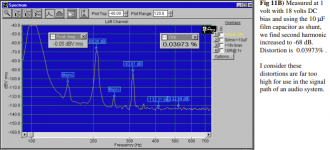
I can hear -60dB noise or artifacts when I know how the artifact sounds and I'm listening for artifacts not music. At casual listening levels actually listening to music I hear artifacts at -40dB. So any noise -60dB below signal level would be below my hearing abilities. ELNA Silmic + shunt might be the only combination in my hearing range. (It's just -30dB below signal level)
PS. Tantalums were the worst measuring caps according to Bateman, to the point that he droppped those out of his articles entirely. I still have actual lampcords for some of my surround speakers - can't say it makes a difference (for surround)
Attachments
Since R12 is the feedback resistor, it counts as being in the signal path.... R16, and have used 499Ω for higher voltage power rails...
Ok, so I was off by R12 in my initial guesstimate
 ? "My" R16 was the bridge resistor which was 39,2 in the v.1.6 and v1.8 wiring guide. "Your" R16 at 499Ω is the first time I'm hearing about it and I have read all 60 pages in this thread, but might have missed something. C3 felt way to small at 10uF, I think at 470uF it's 0.7Ω@20Hz. I think it might be by design to keep the highs well above the base. It might even work out nicely if I bi-amp and power my lows with my regular amp and the highs with ACA. I might revisit C3. I might even do Silmic II + 1uF film shunt for those 2nd harmonics.
How about C1?
 I would really like to get rid of that output cap. In bridged mode C1 and C3 will be in series and C1 is then negligible - it will still total out below ~10uF. There shouldn't be any DC in bridge mode - but my knowledge is purely theoretical and I might be very wrong??
Attachments
Last edited:
Do you mean this thread?
My Capacitor comparisons: Mundorfs, VCap, Sonicap Platinum, Auricap, etc
Here is some more on Toroids vs EI-transformers if someone wants to do play around with PSU design:
SoundStage! Max dB - The High-End Mythology of the Toroidal Power Transformer (07/1998)
On the other end of the stick, here are some measurements showing no difference on caps and resistors:
Replace resistor by low-inductance resistor - Is it audible? | Audio Science Review (ASR) Forum
Capacitor upgrade in crossover - Is it audible? | Audio Science Review (ASR) Forum
Here is one on a knife edge about his Mundorf caps:
Reviews, Reports & Rambling - PRAIRIE AUDIO MAN CAVE
The reading doesn't stop:
https://www.vhaudio.com/21capacitorshootout.pdf
http://www.enjoythemusic.com/diy/0708/capacitor1.htm
http://www.enjoythemusic.com/diy/1108/capacitor1.htm
http://www.enjoythemusic.com/diy/0411/capacitor1.htm
I might just get some 25mm or 50mm copper foil, som mylar foil and start rolling and save a few hundred dollars.
C1 is absolutely necessary, even in bridged mode. It blocks DC voltage from appearing at the output of the amp.How about C1?
C1 is absolutely necessary, even in bridged mode. It blocks DC voltage from appearing at the output of the amp.
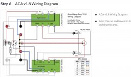
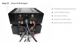
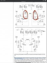
I ment ”Balanced Mono” or ”MONOBLOCK bridged with XLR”. Have a look at the wiring diagram, speakers are connected to OUT- which will BOTH have +12VDC offset and see 0VDC over the speakers. Similar info is mention in Zen Variations I’ve marked them with red. If Nelson Pass can remove coupling caps so can we - right?
With C1 gone, C3 is not really an issue, although I would still go 470uF and maybe Elna Silmic + film shunt to visit those 2nd Harmonics.
Attachments
Ok, for this configuration you will need set the DC offset of each amp very carefully to make sure that there is no DC present at the speaker terminals. Make sure the amps have been burned in at final temperature for at least an hour to ensure there is no drift in DC offset.
Edited to add:
I left C1 in my original ACAs and preferred the parallel bridged configuration. These used the SMPS brick power supplies. When I built the next set of ACAs in the larger chassis with higher voltage linear supplies (300 VA toroidal transformer w/ 24V secondary), I preferred the sound of these to the original parallel ACA. My power rails were running close to 29.5V after CRCRC filtering.
Last edited:
yep😛Do you mean this thread?
My Capacitor comparisons: Mundorfs, VCap, Sonicap Platinum, Auricap, etc
If you eliminate C1, now you have DC on the feedback loop and DC coming out the input. C3 may be reverse biased depending on how your input source deals with the DC. If your source has an electrolytic cap on it's output, it may also be reverse biased.
Hi again
after very long pause i restart my ACA premium. i checked all my IRFP240 like written in nelson pass document MOSFET _ART_matching. 15V supply and GD is connected and then measure current and Vgs. i want to have more current and use R1= 100R , R2= 56R, R3 = R1//R2=35,9R
i test all my 20 pcs of IRFP240 by Reichelt and digikey. So i measure 3 times with on MOSFET and write the values down. at some MOSFET i try different thing and that is the table on the right side.
IRFP240_MOSFET_matching.pdf
i marked the pair with different colors. Is my measurement useful for ACA and my future project M2?? or should i do something different?
thank you in advance
chris
Attachments
It sounds like you have done plenty to get a good matched Mosfets.
To be honest, I haven't spent that much time matching devices. I usually order 20 or 24 and am satisfied with devices from the same manufacturing lot.
Edited to add:
Since the ACA does not use transistors in parallel, it is not very sensitive to matching. If you decide to build an Aleph J or a BA-3, then your carefully matched transistors will be very nice to have.
Last edited:
Thank you TungstenAudio
if you read my other posts pages before i am planning to do in the future some bigger ACA with 2 FET´s in parallel😉🙂.....but not now...
i am busy with non audio stuff..🙁
if you read my other posts pages before i am planning to do in the future some bigger ACA with 2 FET´s in parallel😉🙂.....but not now...
i am busy with non audio stuff..🙁
Hey all,
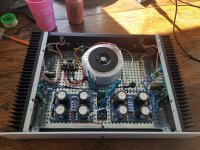
Looking for some advice on my recently completed ACA build. I followed most of the modifications outlined by Tungsten, and am using a dual, single-rail linear supply based off of the DIYA PS board with a 300VA, 20V secondary transformer.
I am getting around 28V on the PS outputs, have set the DC balance to 14V at pin 2 of Q1, and am measuring a 0.192V drop across the PS resistors (4x 0.47 Ohms). I think this equates to 1.63A of current draw per channel at idle, or about 46W per channel. The build is enclosed in a 2U Dissipante chassis, also from the store, and the heat sinks get quite hot after a while - but still cool enough to hold my hand on. Will running the amp at this power level shorten the life of the transistors?
Additionally, the top panel of the chassis doesn't want to close, due to the height of the 300VA transformer sitting on top of the baseplate. Will moving to a 200VA transformer cause any problems? The combined power draw of the 2 channels is about 90W, so I wouldn't think it would be an issue, but I am no expert.
Any insight would be appreciated!
Thanks.
Attachments
... but still cool enough to hold my hand on. ...
Totally normal.
... Will moving to a 200VA transformer cause any problems? ...
No.
Very nice looking build.

- Home
- Amplifiers
- Pass Labs
- ACA amp with premium parts