My ACA is running one channel only while waiting to receive a second pair of SemiSouth SJEP120R100 since I finally placed my two existing on both Q1 and 2. It's just soo much better han 44N10, that I skip other further comparisons. I am done also fiddling, because very busy at work latelly, but when I receive the expensive power Jfets, I will be more interested in complete the stereo.
Jordi
Jordi
Attachments
Hi All, Hope all Builds are coming along nicely. I just tried out the FireMetall Solder for the first time on my ongoing Oppo 205 upgrade project, this stuff is great.
Moto
Moto
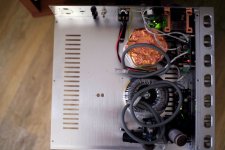
Thought I would share some pics of my ACA 18 "Premium" Parts build. This my first build since I built my Hafler DH-101 more years ago than I care to remember...
Photos from my wondrous little Fujifilm X100F, shot with available light and/or TTL fill. These photos also show the Nichicon Gold Tune cap at C1 and the aluminum organic polymer Nichicon caps at C2 and C4 per Tungsten's recommendations.
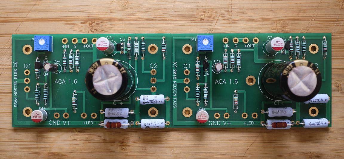

Single board close up...still have to get in the 10pF silver mica bypass cap for R12 that James (TungstenAudio) recommends.

Rear of the stuffed boards

Rear panel connector assembly...


More pics to follow as I wire everything up...
Photos from my wondrous little Fujifilm X100F, shot with available light and/or TTL fill. These photos also show the Nichicon Gold Tune cap at C1 and the aluminum organic polymer Nichicon caps at C2 and C4 per Tungsten's recommendations.
Single board close up...still have to get in the 10pF silver mica bypass cap for R12 that James (TungstenAudio) recommends.
Rear of the stuffed boards
Rear panel connector assembly...
More pics to follow as I wire everything up...
Last edited:

Thanks, James.
Yes, the new 1.8 panel is very informative for making connections for different operational configurations.
Just have a couple more parts to order to get in the rest of the remaining bits in so I can finish up both amps. One of the things I will do is post a list of the parts with PN's and Manufacturer Numbers from Mouser Electronics so folks will know what to order all at one place.
Last edited:
Looking Good!
Your boards are looking good. Wait till you hear them sing, the proof
of the pudding!!!🙂
Your boards are looking good. Wait till you hear them sing, the proof
of the pudding!!!🙂
Thought I would share some pics of my ACA 18 "Premium" Parts build. This my first build since I built my Hafler DH-101 more years ago than I care to remember...
Photos from my wondrous little Fujifilm X100F, shot with available light and/or TTL fill. These photos also show the Nichicon Gold Tune cap at C1 and the aluminum organic polymer Nichicon caps at C2 and C4 per Tungsten's recommendations.
Single board close up...still have to get in the 10pF silver mica bypass cap for R12 that James (TungstenAudio) recommends.
Rear of the stuffed boards
Rear panel connector assembly...
More pics to follow as I wire everything up...
Thank you for the info on the Vishay resistors used in the kit, Variac.
Very helpful. It can be confusing as to which Vishay resistors to order for replacements or substitutions because there is Vishay, Vishay Beyschlag, and Vishay BC.
Decisions, decisions! 😕
😀
Very helpful. It can be confusing as to which Vishay resistors to order for replacements or substitutions because there is Vishay, Vishay Beyschlag, and Vishay BC.
Decisions, decisions! 😕
😀
Last edited:
So one issue with resistor ratings is that some are specified as military spec, which is half the watt rating of regular commercial resistors. Thats why there are resistors that are the same size but with double or half the rating..
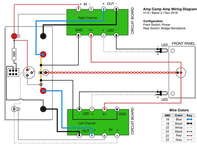
So...I've run across a perplexing problem. I'm wiring the rear panel before soldering the various wires to the boards, and....the resistor that goes from the lower right terminal on the switch to an input RCA jack in versions 1.6, Batch 3 as shown here:
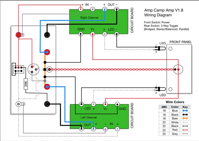
However, in the new wiring diagam for version 1.8, the 68.1K resistor that James recommended goes from the lower right terminal on the switch goes to the left channel negative binding post output (see part of wiring schematic for version 1.8 highlighed by red box as shown).

Is this correct?
One of the issues that I have is that the 68.1k Ohm Resistor that James specified...does not reach from the lower right terminal on the switch to the lug on the binding post.
Is this correct or mis-drawn? I'm confused because the resistor connects from the switch to an input in the earlier version, but to an output in version 1.8. 😕
And...the other thing I find confusing is that the rationale for changing this resistor connecting the switch from an input connection to an output connection is not specified, either (at least that I could find). 😕
Any help folks can provide most welcome as I am presently actively wiring up my ACA '18.
Thanks, gents.
However, in the new wiring diagam for version 1.8, the 68.1K resistor that James recommended goes from the lower right terminal on the switch goes to the left channel negative binding post output (see part of wiring schematic for version 1.8 highlighed by red box as shown).
Is this correct?
One of the issues that I have is that the 68.1k Ohm Resistor that James specified...does not reach from the lower right terminal on the switch to the lug on the binding post.
Is this correct or mis-drawn? I'm confused because the resistor connects from the switch to an input in the earlier version, but to an output in version 1.8. 😕
And...the other thing I find confusing is that the rationale for changing this resistor connecting the switch from an input connection to an output connection is not specified, either (at least that I could find). 😕
Any help folks can provide most welcome as I am presently actively wiring up my ACA '18.
Thanks, gents.
Last edited:
Yes.
This first diagram is the Batch 3 version wiring diagram for ACA 16. Note the bridging resistor is connected from the lower right terminal on the switch to the right channel RCA input.
The second diagram is the ACA 18 wiring diagram. Note that the 68.1K Ohm bridging resistor (shown here as the original 39k resistor) is connected from the lower right switch terminal to...the left channel negative binding post (output). 😕
An externally hosted image should be here but it was not working when we last tested it.
Hi All, The ACA 1.8 Build Guide has been updated with some useful information:
Amp Camp Amp V1.8 Build Guide - diyAudio Guides
Mark
Amp Camp Amp V1.8 Build Guide - diyAudio Guides
Mark
Yes.
:
For some reason I don't see the second circuit diagram
Unfortunately, the wiring diagram in the 1.8 build guide still does not explain WHY the bridging resistor has moved from the R Channel RCA input to the L Channel negative OUTPUT.
For some reason I don't see the second circuit diagram
Sorry...I can see it, so I don't know why you can't, but I will put it up again...just a sec.
Okay...once more around the block.
Wiring diagram for ACA 16 Batch 3:
Wiring Diagram for ACA 18:
So....what I don't understand is why the bridging resistor that was originally connected from the lower right switch terminal to the input of the R channel RCA in ACA 16 is now connected to the Negative Output of the L channel (speaker binding post) in ACA 18.
And...the specified resistor does not reach from the negative binding post to the lower right switch terminal, either...🙁
Last edited:
I can see both now.
Ok the only difference is the side of the switch the resistor is on.
When the switch is closed it doesn’t matter what side of the switch the resistor is on they will both be connected in the same way.
When the switch is open, the resistor is not part of the circuit in either case so it’s still good.
I am assuming the switch is a dual pole dual throw switch, with the switch operated vertically as installed on the chassis.
Last edited:
Thanks for your reply, however, my questions have still not been answered.
Okay, then why does the V1.8 wiring diagram showing the bridging resistor going to the lower right terminal of the switch when the resistor is way too short to connect to the lower right terninal, but it may be long enough to connect to the lower left terminal?
However, I am still as confused as before. This is because while the new v1.8 wiring diagram depicts wiring changes, the context and rationale of WHY these changes were made relative to V1.6 is not provided. As a result, being a newb, I do not undertand WHY these wiring changes were made.
Coming back to the two wiring diagrams, the bridging resistor is connected to the lower right terminal of the switch (why it's specifically connected on the right side and not the left side terminal, I don't understand, either.)
In version 1.6, this resistor used to be connected to a source signal input to the R(ed) channel.
Now, in version 1.8, now the bridging resistor is connected to the L(eft) channel OUTPUT at the speaker binding post.
My questions is: WHY?
When the switch is closed it doesn’t matter what side of the switch the resistor is on they will both be connected in the same way.
Okay, then why does the V1.8 wiring diagram showing the bridging resistor going to the lower right terminal of the switch when the resistor is way too short to connect to the lower right terninal, but it may be long enough to connect to the lower left terminal?
This is a 3-pole, 3-throw switch, with a "top", "middle", and "bottom". When the switch is in the middle position, the amp runs as a stereo amplifier.Ok the only difference is the side of the switch the resistor is on.
However, I am still as confused as before. This is because while the new v1.8 wiring diagram depicts wiring changes, the context and rationale of WHY these changes were made relative to V1.6 is not provided. As a result, being a newb, I do not undertand WHY these wiring changes were made.
Coming back to the two wiring diagrams, the bridging resistor is connected to the lower right terminal of the switch (why it's specifically connected on the right side and not the left side terminal, I don't understand, either.)
In version 1.6, this resistor used to be connected to a source signal input to the R(ed) channel.
Now, in version 1.8, now the bridging resistor is connected to the L(eft) channel OUTPUT at the speaker binding post.
My questions is: WHY?
The answers to your questions are mostly.
1) It doesn't matter so no explanation is given
2) Papa constantly changes the way he does circuits - maybe out of boredom, maybe to get people to think and not just copy.
1) It doesn't matter so no explanation is given
2) Papa constantly changes the way he does circuits - maybe out of boredom, maybe to get people to think and not just copy.
- Home
- Amplifiers
- Pass Labs
- ACA amp with premium parts