The answers to your questions are mostly.
1) It doesn't matter so no explanation is given
2) Papa constantly changes the way he does circuits - maybe out of boredom, maybe to get people to think and not just copy.
Hi Pico,
I sincerely appreciate you are taking time to answer my question.
However, I'm still confused. If the change doesn't matter, why was the wiring change made in the first place? Whle I am very clearly not a EE, I am a scientist, and in my professional career, I adhered to the maxim, "If it's not broken, don't fix it."
So...I am still where I started: I don't understand the reason WHY the change of the wiring of the 68.1K bridging between V1.6 and V1.8 was made.
Especially as this resistor was originally connected from the switch to a INPUT, and and now it is connected to an OUTPUT.
I really value and appreciate all the input from this community, sharing idea and knowledge so we can have fun building some cool amplifiers.
However, when changes are made to circuit topologies are made, and no CONTEXT and RATIONALE for these changes is given, it can be very difficult for newbies and non-EE's to UNDERSTAND and LEARN why these changes were made.
Thanks again for taking the time to reply. 🙂
The bridging resistor is 39K.
In both versions (1.6 and 1.8) when the switch is thrown to engage the RCA bridge mode, the resistor is connected between the right RCA and the left output.
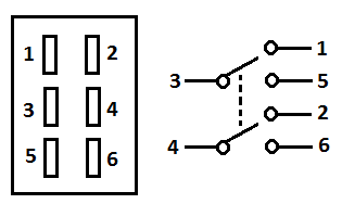
The actual location of the resistor is immaterial, you could absolutely put it between the RCA and the switch. Make sure you connect the 39K resistor to terminal 4 and the speaker post to terminal 6.
In both versions (1.6 and 1.8) when the switch is thrown to engage the RCA bridge mode, the resistor is connected between the right RCA and the left output.
The actual location of the resistor is immaterial, you could absolutely put it between the RCA and the switch. Make sure you connect the 39K resistor to terminal 4 and the speaker post to terminal 6.
Last edited:
Thanks, Jim.
This information is helpful for my understanding.
Just a note, back in the first few posts of this thread, TungstenAudio recommended changing the bridging resistor from a value of 39K to a value of 68.1K. His rationale (thank you, Tungsten, for providing the rationale!) is here:
Post link here: https://www.diyaudio.com/forums/pass-labs/328357-aca-amp-premium.html#post5568768
This information is helpful for my understanding.
Just a note, back in the first few posts of this thread, TungstenAudio recommended changing the bridging resistor from a value of 39K to a value of 68.1K. His rationale (thank you, Tungsten, for providing the rationale!) is here:
Given how good the ACA sounded as a simple stereo amp, I really wanted to try a pair as bridged mono blocks. Since I had modified the input and feedback resistors, I knew that a different resistor value would be required between channels to make a bridged amp. After some experimentation, I settled on a value of 68.1k from the left (-) output to the right input. My experience plus some other findings on the Pass forums suggest that the standard recommendation of using the same value as the feedback resistor is not the best way to go.
Post link here: https://www.diyaudio.com/forums/pass-labs/328357-aca-amp-premium.html#post5568768
If one has a modified ACA with 20k for R11 and 90.9k for R12, then the bridging resistor needs to be 68k in order to balance the levels of the two boards.
Hi Pico,
I sincerely appreciate you are taking time to answer my question.
However, I'm still confused. If the change doesn't matter, why was the wiring change made in the first place? Whle I am very clearly not a EE, I am a scientist, and in my professional career, I adhered to the maxim, "If it's not broken, don't fix it."
Yes, but you need to understand Papa's psychology.
He likes to hurt our brains.
Hahahaha
Or think of it this way.
If you could write just as well right handed as you could left handed, would you occasionally use the other hand.
This is so obviously not an issue to Papa, he doesn't even see it as being different, cause it's not.
Or kind of like walking with 2 legs, why would you want to hop all day long.
Last edited:
If one has a modified ACA with 20k for R11 and 90.9k for R12, then the bridging resistor needs to be 68k in order to balance the levels of the two boards.
Exactamundo.
Yes, but you need to understand Papa's psychology.
He likes to hurt our brains.
Hahahaha
Or think of it this way.
If you could write just as well right handed as you could left handed, would you occasionally use the other hand.
This is so obviously not an issue to Papa, he doesn't even see it as being different, cause it's not.
That's all well and good, but with all due respect to fine folks here and Papa, I don't know that. I'm a newb that can read a schematic and wiring diagram and make connections, but I don't know why the connections are what they are. I'm just (trying) to follow the (ambiguous) instructions in the build guide.
I really don't want to come across as argumentative here, but if a wiring change results in virtually no functional difference with respect to circuit topology, then why make the change to the wiring diagram between V1.6 and V1.8 in the first place?
Especially when the resistor is not long enough to reach from the L output to the switch terminal. 🙁
Last edited:
Yeah
Don't worry. I was in the exact same place.
I think I've read all of Papa's articles more than 10 times each over a period of many years, every time I have read them, I notice something new I didn't even realise was there previously.
They are written like bloody riddles it seems.
Each time you read them you understand more.
thanks, Pico.
Jim (6L6) helped me out to understand what's going on.
And, I appreciate your being proactive in helping to understand my questions.
Cheers and thanks!
Stephen aka PC
Jim (6L6) helped me out to understand what's going on.
And, I appreciate your being proactive in helping to understand my questions.
Cheers and thanks!
Stephen aka PC
Long Enough 🙂.
You can just cut of the lead of a spare resistor and solder them together, and insulate it if you want.
Mark
That's all well and good, but with all due respect to fine folks here and Papa, I don't know that. I'm a newb that can read a schematic and wiring diagram and make connections, but I don't know why the connections are what they are. I'm just (trying) to follow the (ambiguous) instructions in the build guide.
I really don't want to come across as argumentative here, but if a wiring change results in virtually no functional difference with respect to circuit topology, then why make the change to the wiring diagram between V1.6 and V1.8 in the first place?
Especially when the resistor is not long enough to reach from the L output to the switch terminal. 🙁
You can just cut of the lead of a spare resistor and solder them together, and insulate it if you want.
Mark
thanks, Pico.
Just so you know.
The switch shown by 6L6 is refered to as a dual pole dual throw switch.
You can get them in either On-On, or On-Off-On style.
Yes, understood.
The switch provided with the V1.8 kit has three settings; it is an On-Off-On style.
The switch provided with the V1.8 kit has three settings; it is an On-Off-On style.
Last edited:
Correct. Both are DPDT, but;
1.6 has a on-on,
1.8 uses a on-off-on.
Yes, thanks so much, Jim.
Very helpful info. Actually, the picture you posted of the switch was the most helpful as it let me understand (there's that word again...) the distinctions between a 2-pole switch with On-On settings and a 2-pole switch with On-Off-On settings.
Last edited:
I designed the switching and wiring of the 1.8 version. The priority for me was to be sure it works. In addition, getting the rear panel to be graphically logical, and the text concise was no small task! Finally coordinating the internal wiring with the rear panel was another task.
Obviously the switch needs to be changed out, so wiring is going to be changed anyway and functions exactly the same...the resistor is just on opposite side of the switch. As far as the resistor length, that admittedly wasn't a big priority. I'll revue it so I can explain it more clearly. And if you now realize that the wiring still works the same, but does more!, then you've learned something.
Obviously the switch needs to be changed out, so wiring is going to be changed anyway and functions exactly the same...the resistor is just on opposite side of the switch. As far as the resistor length, that admittedly wasn't a big priority. I'll revue it so I can explain it more clearly. And if you now realize that the wiring still works the same, but does more!, then you've learned something.
Last edited:
I cut the black, fatter (18ga) wire from the Left PCB "-" speaker hole a couple of inches longer, and stripped off the insulation. So after passing through the speaker terminal tab there was an additional 2" of bare wire. it was easy to insert the resistor lead into the multiple strands of the bare wire and solder in place. This gives plenty of length to get the resistor to the switch.
If there's something "clever" about the wiring of V1.8, it's that the L&R center pins of the switch are each connected to an input directly so that when that little shunt connecting the top 2 pins is activated by pushing the switch handle down, the 2 channels are shorted together in parallel. Thus we can't have the resistor going from the center pin to the input as in the 1.6, as this would keep the "clever" part from working. Then if you push the handle up, it "cleverly" connects the resistor, and disconnects the shunt.
Last edited:
f there's something "clever" about the wiring of V1.8, it's that the L&R center pins of the switch are each connected to an input directly so that when that little shunt connecting the top 2 pins is activated by pushing the switch handle down, the 2 channels are shorted together in parallel. Thus we can't have the resistor going from the center pin to the input as in the 1.6, as this would keep the "clever" part from working. Then if you push the handle up, it connects the resistor, and disconnects the shunt.
Ah, this is good to know. For my ACAs, I've got the bridging resistor on pin 6, and the wire from the L speaker output connected at Pin 4, per the instructions above from Jim (6L6).
- Home
- Amplifiers
- Pass Labs
- ACA amp with premium parts