Hello everyone, just to update you I have now purchased the regulators from Rod, and will build myself a DC supply to feed based this upon some repurposing of the existing DC supply (new diodes STPS1545D )
I will also go through the exercise of listening to AC first as it's not a huge amount of work, and I can share my listening experiences in my system.
With respect to using AC for the first trial then I have a couple of questions.
I will also go through the exercise of listening to AC first as it's not a huge amount of work, and I can share my listening experiences in my system.
With respect to using AC for the first trial then I have a couple of questions.
- If I find the 10.5AC quoted creates to high AC across the filament (I will put a dummy load to see) then is it just a simple job of adding a small value power resistor on each side of the AC line. This would be pretty simple as I am going to join to the existing twisted line from the transformer and I can just add two series resistors here on each wire.
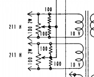
- When I run the AC into either dies of he balance pot, I see many circuits also utilising two fixed resistors (e.g. Ongaku schematic with image attached) that run across either end of the pot to the cathode/wiper connection. I presume I just follow this approach, and add these resitors to the install.
- When I wire my AC as a twisted line, there was an earlier IMO great idea of also twisting the last leg of the install (thankyou Hearinspace!) with a blind(un connected) wire to keep the twisted affect. I am still unsure if this works even when there is no current flowing in the blind lead, any smarter than me dudes care to comment?
Attachments
Really nice that you're actually posting a follow-up. That doesn't always happen.
I've never seen it done the way shown in your posted screenshot and don't know what benefit that way of doing it might be outside of its use with the Ongaku's grid bias scheme.
I'm used to seeing the added resistors at each end of the potentiometer's resistance element (not connected to the wiper), limiting the pot's balancing influence to a narrower band either side of centre and making the set voltage more finely tuneable.
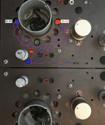
I have never measured the influence of the extended run (or lack of it) but for all the work it entails it seemed like a good idea on a very tight phono circuit I built a few years ago that came out very quiet and so I just keep doing it whenever quiet is the chief concern in situations with very tight spacing. I doubt you'd see any difference at all on your circuit without it. (I didn't use it on the Coleman regs in the pic I posted.)
Is your 10.5VAC winding centre-tapped?
I've never seen it done the way shown in your posted screenshot and don't know what benefit that way of doing it might be outside of its use with the Ongaku's grid bias scheme.
I'm used to seeing the added resistors at each end of the potentiometer's resistance element (not connected to the wiper), limiting the pot's balancing influence to a narrower band either side of centre and making the set voltage more finely tuneable.
I have never measured the influence of the extended run (or lack of it) but for all the work it entails it seemed like a good idea on a very tight phono circuit I built a few years ago that came out very quiet and so I just keep doing it whenever quiet is the chief concern in situations with very tight spacing. I doubt you'd see any difference at all on your circuit without it. (I didn't use it on the Coleman regs in the pic I posted.)
Is your 10.5VAC winding centre-tapped?
Twisting two conductors together works to minimize coupling in and out because, at a distance, it averages the fields of the two wires, and because the destination is differential, meaning being sensitive to (only) the difference between the two wires. It must have "common mode rejection". Simply corkscrewing a wire has no effect on external coupling.
There's likely no advantage to splitting your dropping resistors into halves - transformer secondaries aren't symmetrical anyway - but it doesn't hurt. Live it up. Be sure to size them to survive turn-on cold filament current for a few seconds. Instead of hot load of about 3R, for a few seconds you have a cold load of maybe 0R6, fairly serious. As R. Coleman has made clear, you want a hot filament voltage of 9.5 Volts (RMS or DC).
Another option for balancing trim pots is to use a much larger value than the main current carrying resistors. I like 50R main resistors and a shunt 1K pot. This lightens the DC current through the pot's wiper (for longetivity) and makes it a finer adjustment (less sensitive). If you're careful in its use, you can make a headphone adaptor from speaker outs directly to headphones, no attenuation, for easiest zeroing of these trims.
All good fortune,
Chris
I do really appreciate all the help from everyone as I learn more.Really nice that you're actually posting a follow-up. That doesn't always happen.
yeah I found this this also and the extra resistors may be a safety in case the pot lost contact.I've never seen it done the way shown in your posted screenshot and don't know what benefit that way of doing it might be outside of its use with the Ongaku's grid bias scheme.
I'm used to seeing the added resistors at each end of the potentiometer's resistance element (not connected to the wiper), limiting the pot's balancing influence to a narrower band either side of centre and making the set voltage more finely tuneable.
going to just do it anyway > this is an unconnected circuit experiment here I think.I have never measured the influence of the extended run (or lack of it) but for all the work it entails it seemed like a good idea on a very tight phono circuit I built a few years ago that came out very quiet and so I just keep doing it whenever quiet is the chief concern in situations with very tight spacing. I doubt you'd see any difference at all on your circuit without it. (I didn't use it on the Coleman regs in the pic I posted.)
unfortunately it's not centre tapped. just to 0-10.5VIs your 10.5VAC winding centre-tapped?
I can't help but wonder if that isn't a response to the wiring in my posted pic. It never occurred to me it might be interpreted that way, so maybe not.Simply corkscrewing a wire has no effect on external coupling.
I simply had a twisted pair in the drawer and backed them apart enough to get to the socket lugs.
Funny, now I can imagine somebody sitting there with a chopstick, coiling their hookup wires . . . . . .
Attachments
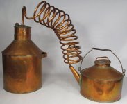
Arf! White lightnin'.
I was just trying to respond to post #121 question 3, but I explained it poorly. For radiated noise cancellation (at a distance) from twisting to work requires that the same amount, but opposite polarity, current flow in both of the twisted conductors. A "blind" conductor has no effect at all, and behaves like a single corkscrewed wire. This would also be the case for a coaxial pair with one conductor not connected.
The same reasoning applies to received noise cancellation, but explicitly requires a differential termination.
All good fortune,
Chris
I'm not sure about that actually. What about electrostatic field? Yeah yeah I know, 10VAC isn't going to expand the ionosphere but a field is a field. I need to get me a test probe. Where's Elvee's HumBoy probe when you need one?A "blind" conductor has no effect at all, and behaves like a single corkscrewed wire.
You're right, of course, but in the context of 3R impedances, multiple-Volt levels, and a beginner level discussion, how far into the weeds is appropriate? If we were discussing line level signals at 10K impedances, all the simplifications go away, and a more complete model would be needed, fersure. But not really for this situation.
All good fortune,
Chris
All good fortune,
Chris
My thoughts.
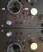
If doing it as though permanent I'd probably do it something like how I drew it, where the side by side runs represent twisted pairs. But it all depends on what you actually have to navigate around in the circuit.
If it's an experiment first, no need to wire it all professional finish like. I'd start with a more 3d layout. Twisted pair hanging down and away from the AC source and circuitry, rising up again to make the connection from under the socket. Simple and almost nil chance of getting hum from the wiring. Then, if there's audible hum , you know it's not the wiring but just the fact of AC powered filament. If on the other hand you like what you hear, then you can set about figuring how to do finished wiring without introducing unnecessary additional hum.
I always keep in mind a story I heard about how Telefunken got their old tube radio receivers so tightly packed with transformers, components and wiring all snugged up together. Lots of engineers and techs, trying it this way and that until they got it quiet.
Attachments
thanks, due to room restrictions and access without taking too many things off the amp, I will probably prepare the pot with all the necessary twisted prepared leads and then pop this into the unit, I will keep a record when I get around to it 🙂 and share for those who might have an interestMy thoughts.
If doing it as though permanent I'd probably do it something like how I drew it, where the side by side runs represent twisted pairs. But it all depends on what you actually have to navigate around in the circuit.
If it's an experiment first, no need to wire it all professional finish like. I'd start with a more 3d layout. Twisted pair hanging down and away from the AC source and circuitry, rising up again to make the connection from under the socket. Simple and almost nil chance of getting hum from the wiring. Then, if there's audible hum , you know it's not the wiring but just the fact of AC powered filament. If on the other hand you like what you hear, then you can set about figuring how to do finished wiring without introducing unnecessary additional hum.
I always keep in mind a story I heard about how Telefunken got their old tube radio receivers so tightly packed with transformers, components and wiring all snugged up together. Lots of engineers and techs, trying it this way and that until they got it quiet.
oh quick probably dumb to the already knowledgable question:
If i look at power resistors ( I am going to use a dummy load to represent the filaments as I check the voltages) and I read the specifications in relation to a heat sink to match the rating. Then the quoted figures are for a 1mm panel with a cross sectional area / BUT when I look at heat sinks they quote a DegC/watt - how do I correlate these to make sure I am not overheating my power resistors in the dummy load ?
Thanks,
Member
Joined 2009
Paid Member
DegC/Watt is how many degrees the temperature of the sink will increase per watt of power dumped into it. You want to keep the sink around 50degC, maybe 60C (for safety reasons not to burn yourself). If room is 22C then you want no more than a 30C or 35C rise. If your sink is 2 DegC/Watt then you can feed it with 30/2 = 15W to 35/2 = 17W power max
If you can avoid burning yourself then you can go much hotter.
If you can avoid burning yourself then you can go much hotter.
As a practical example: using 2mm thick Aluminium plate, 200mm x 200mm, standing vertically in free air, the thermal resistance is about 2.5 °C/W. This should be OK for the dummy load resistor for 211. this may be too hot to touch if you soak-test it for a long interval, but as it's a temporary test, and suitable caution can/should be applied.
Those Alu-clad resistors can withstand very high temperatures, so I wouldn't use their figures as first choice!
Those Alu-clad resistors can withstand very high temperatures, so I wouldn't use their figures as first choice!

Rod thanks,As a practical example: using 2mm thick Aluminium plate, 200mm x 200mm, standing vertically in free air, the thermal resistance is about 2.5 °C/W. This should be OK for the dummy load resistor for 211. this may be too hot to touch if you soak-test it for a long interval, but as it's a temporary test, and suitable caution can/should be applied.
Those Alu-clad resistors can withstand very high temperatures, so I wouldn't use their figures as first choice!
Can I set each channel separately so I only have to have one heat sink set up and one dummy load, or do they need to run in tandem simultaneously with a load?
Much better to test separately.Rod thanks,
Can I set each channel separately so I only have to have one heat sink set up and one dummy load, or do they need to run in tandem simultaneously with a load?
The aim of the test is to check that there are no solder joint failures, shorts etc; and then check the DC stability.
Keeping a close eye on it for this test is essential - and unless you have a skilled assistant, it's difficult to do for >1 units at a time!
ok - great! much easierMuch better to test separately.
The aim of the test is to check that there are no solder joint failures, shorts etc; and then check the DC stability.
Keeping a close eye on it for this test is essential - and unless you have a skilled assistant, it's difficult to do for >1 units at a time!
Following up on the suitability of the voltages and choice of diodes, I have been trying to make sense of things from some measurements I made on the amplifier without any stripping down.
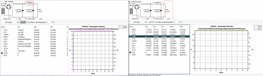
Here are two plots using PSUD2 which I am starting to become familiar with. I used some of the capability of this to hypothesise the internal transformer resistance as I did not measure this directly. This seems to suggest that with Diodes with a low forward voltage I should be able to get to 13.3V as I am getting 10V DC now across the valve and measured about 2.4V across the R82 resistor.
I have modelled a 200 mOhm resistor and used STPLS20L25 diodes
I have a hum pot in the circuit too and I don't really know how to model that.
I have had to increase the voltage at the transformer to get the simulations to create the measured outcomes.
Input welcome 🙂
Attachments
Hi Rich
The original diodes you have were on a board marked 300B - and I think that's why they are under-rated. The types I use will give much lower drop ar high current (the only place it matters!).
With PSUD2, the built-in type 1N5828 comes close, use that for your estimates; 1N5822 is nearer to the 300B version
PSUD2 PT voltage is the unloaded voltage - easy to measure
You can easily measre the t5ransformer resistance without having to strip it down.
Just wait for the reading to stabilize - the transformer wiring will anyway be the lowest resistance in the circuit so whatever it is connected to will not matter much.
Jan
Just wait for the reading to stabilize - the transformer wiring will anyway be the lowest resistance in the circuit so whatever it is connected to will not matter much.
Jan
- Home
- Amplifiers
- Tubes / Valves
- AC Heater for better Sound quality? Waste of time or worth a try