Not "year" per se but design or functionality.Complaining about a tube being old in a tube forum is laughable. Is there cutoff year for what's acceptable and what is not?
DHT tubes have been obsolete since the 30´s, for God´s sake!
Originally designed because they didn´t know better, when cathode coating had not yet been invented so they were the most "efficient and simple" ones, again by 1920´s and 30's standards that is.
And of course, Radios and amplifiers were battery powered, literally, that´s where still current names of supplies come from.
"A" batteries being typically a single lead acid cell so around 2V or a carbon zinc at 1.5V
"B" batteries (we still talk about "+B" supply 😉 )
"C" batteries for bias.... used before the technically advanced self biasing cathode resistor was invented 😱
Of course, in HV rectifiers, transmitting tubes, etc. the DHT quirks and disadvantages can be tolerated.
Going backwards, big time, and accepting or even applauding performance degrading technologies stinks of superstition.
Of course, "birds of a feather flock together" so Believers meet each other here and reinforce the echo chamber threads.
https://en.wikipedia.org/wiki/Echo_chamber_(media)
GLORY days of the DHT tube, when it was King of the Hill:


The 'others' you address were probably well aware of echo chambers. How about instead considering the inherent linearity of many of these old tubes and the modern techniques available to unlock that potential?people people people
Hi 6A3,
At what cost is it reasonable to pursue perfection with an imperfect technology??? When you can't hear it, does it matter? Answer - no, it doesn't matter.
Too often people pursue technical details past what is required. That's fine as long as the costs and reliability are not compromised. I'll be honest, if I hear a light hum in tube equipment, even stuff I designed and built, I accept it. However my hums levels are lower than you can hear. But I will not go to massive lengths to reduce hum levels below what is needed. I won't tolerate hum in my solid state equipment because it isn't prone to this issue.
I would suggest that people take a reality check when looking at these issues and just be reasonable. Fix the problems but don't chase perfection.
Nope, not at all. As long as the levels are below what you can hear. No difference between music and test tones except that music masks it better.Do you care about those 2 extra tones that were not originally on the test signal?
Do you care about those 2 extra tones that were not originally on the music signal?
At what cost is it reasonable to pursue perfection with an imperfect technology??? When you can't hear it, does it matter? Answer - no, it doesn't matter.
Too often people pursue technical details past what is required. That's fine as long as the costs and reliability are not compromised. I'll be honest, if I hear a light hum in tube equipment, even stuff I designed and built, I accept it. However my hums levels are lower than you can hear. But I will not go to massive lengths to reduce hum levels below what is needed. I won't tolerate hum in my solid state equipment because it isn't prone to this issue.
I would suggest that people take a reality check when looking at these issues and just be reasonable. Fix the problems but don't chase perfection.
Tonescout, one more opinion.
Apparently your interest is being sparked by testimony that AC sounds good. No question that differences can be there. The thing is whether your question will be satisfied by the testimonies of others or not.
You have a ready made experimental platform. Easy enough to bypass the DC filter (leaving it in place) and renew the connections for the original circuit.
The only shortcoming I see is that unless the secondary you have is capable of higher current (to support other options) or you have another power transformer you can outboard for experiments, it will only give you the comparison of the two without exploration of many other options (only matters it you're interested in a wider exploration of course)
But while you're under the hood this is a good time to remember Eimac's advice on extending tube life which for a transmitter like the 211 is to reduce the filament voltage by 5% once it has been run for at least 200 hours at its nominal rated voltage. So for the 211 as low as 9.5V.
BTW, like many others here I'm a long time fan of Rod's supply boards but still think there are times when it makes sense to go AC. If your 10.5VAC winding has a precisely centred centre-tap it may be worth a try as per Kay's mention above, ie with the cathode bias string in series with the CT.
Everything I said above is only to support you getting your own ear's answer to your question and not trying to tell you that AC is definitely better, though again, in the right circuit it can have its charms.
AC filaments are more efficient.
211 spec is 10v @ 3.5A; that requires 3.5A from the filament secondary.
211 can also be run from DC, it still requires 3.5Amps DC to get the same heating as 3.5Amps AC.
But a diode full wave supply, or a bridge supply that feeds either a CRC filter, or a CLC filter requires
3.5 Amps AC x about 1.8 = About 6.3 Amps AC from the transformer secondary to get 3.5 Amps DC.
Efficiency could be a factor, or might not be a factor, you decide.
Using a 3.5 Amp AC secondary to drive a rectifier and either a CRC filter or a CLC filter to get 3.5 Amps DC, will very seriously heat up the 3.5 Amp AC secondary.
As to the sound, yes, definitely listen to both AC filaments and DC filaments, for yourself on your amplifier as it is used in your system.
Just restore one channel to AC filament, and you can listen to AC on that channel, and DC on the other channel.
Connect a RCA phono splitter connector: female to double male, and run both channels from the same music signal,
either Left only, or Right only from your CD player or your preamp to the RCA splitter adapter.
Use the balance control, or whatever other method so you can hear one channel at a time, and also hear both channels at once.
If you go to all that trouble, would you Please give us a report on how your system sounds on AC versus DC.
Thanks for these thoughts. The amplifier is crazy heavy and so it is not a trivial exercise to move and modify test. Consequently I spend a lot of time thinking about what I will do and preparing for it diligently as it is really a 2 man job to move, and whilst I have done this on my a few times it comes with considerable risk as it's on a wall shelf with 250 Kg rated brackets!!Tonescout, one more opinion.
Apparently your interest is being sparked by testimony that AC sounds good. No question that differences can be there. The thing is whether your question will be satisfied by the testimonies of others or not.
You have a ready made experimental platform. Easy enough to bypass the DC filter (leaving it in place) and renew the connections for the original circuit.
The only shortcoming I see is that unless the secondary you have is capable of higher current (to support other options) or you have another power transformer you can outboard for experiments, it will only give you the comparison of the two without exploration of many other options (only matters it you're interested in a wider exploration of course)
But while you're under the hood this is a good time to remember Eimac's advice on extending tube life which for a transmitter like the 211 is to reduce the filament voltage by 5% once it has been run for at least 200 hours at its nominal rated voltage. So for the 211 as low as 9.5V.
BTW, like many others here I'm a long time fan of Rod's supply boards but still think there are times when it makes sense to go AC. If your 10.5VAC winding has a precisely centred centre-tap it may be worth a try as per Kay's mention above, ie with the cathode bias string in series with the CT.
Everything I said above is only to support you getting your own ear's answer to your question and not trying to tell you that AC is definitely better, though again, in the right circuit it can have its charms.
There is a humbucker pot in place so I will use this with my AC trail. One final question is how best to dress the AC twisted cables when I get to the pot to 211 valve wiring, I can't seem to find any images of best practice of dressing cables around the 211 valve base as there will be not insignificant lengths of untwisted AC cables. I presume local shielding of these lengths is a little excessive.
If I measure the 10.5 AC supply at the transformer when it's operating as it is on DC then I can I assume expect this to be maintained when the circuit is returned to pure AC?
I also assume that I can add a small series resistor to attenuate the AC if it's over 10V?
Finally I was interested in Choke input for DC conversion following another article/thread I read is this another pointless rabbit hole....?Q!?
Rich
Uh, anyone who understands the filtering requirements needed for a clean 10 volt 3.5 amp supply. I skimped in my amp because I only used 22,000 uF X 2 caps in each CRC filament supply.Who in their right mind builds a TUBE amp with 47,000uF x2 of filtering?
That's utterly rediculous.
The "Lexan TSE" amp seen in the very first picture on my web site runs some "fossils" that were plucked from an (unrestorable) discarded Sparton radio chassis. The NX-483 tubes had stickers showing that they were installed in 1929. They are still going strong in the same amp which did get a production quality PC board a few years after that picture was taken. Will they live to reach 100 years old? Probably, despite my running them a bit over spec.Checking my TDSL database, I now see this 211 is a directly heated ancient fossil tube.
For a site that touts "Audio Fanatics" loaded with nit-picking members, why would anyone even use such a tube?
Going in the opposite direction of performance would seem silly.
http://tubelab.com/
I had a collection of tubes dating from about 1920 to 1980. There were some 211's and some 845's in that collection. I had already built a 45 based SE amp that would eventually evolve into the Tubelab TSE and then the TSE-II. It is a well liked DHT amp that can use several different "fossil tubes" some of which are still in production (2A3 and 300B). Nearly 20 years ago a friend had started down the DIY path of the Audio Note "poor man's Ongaku" before he got terminally ill. I purchased his parts collection and finished the 211 based amp. As much as I tried, I just couldn't like this amp. It had power and the "DHT sound" but after listening to it for half an hour or more I just wanted to turn it off. It just bugged me, but I had no idea why. I eventually parted out the Ongaku and sold the Audio Note transformers to fund the development of what would become the TSE. I could listen to my prototype TSE all day long and it was indeed running most of the time I was in my lab. The proto TSE was now in it's 5842 driving a DHT form but was still running external power supplies, so swapping from AC to DC and back was as easy as moving a dual banana plug. To my ears the DC heater connection sounded a bit cleaner, but there was not a big difference in the sound. It did seem to me that I was more likely to switch the amp off after some listening with AC filaments.
I decided to rebuild the 211 amp using the TSE audio path as the driver. I really liked the sound of the 45 tube, but 2 WPC didn't "rock" my 87 DB Yamaha NS10M Studio speakers.
I had been experimenting with various vacuum tube breadboarding and prototyping systems at the time. These were called the "Tubelab" which eventually stuck as the company name. Here you can see two of them and the beginnings of the 211 / 845 SE amp. One must understand the risks and safety precautions needed to even think about doing this, especially with a tube that runs on 1050 volts!
http://tubelab.com/articles/tubelab-prototyping-system/
It was determined that the low level (-70 dB) IMD products generated by the AC heating were the source of the listener fatigue. They are too low to be easily heard even with a single tone or guitar note. They do contribute to the overall noise floor, except that this is not random noise. When music with several simultaneous instruments are playing several low level dissonant notes are being generated. together they confuse the brain because they are "irritant tones." My 845SE amp runs DC on the driver (a 45) and output tubes (211's or 845's). I could listen to it forever except for one pesky issue. This amp puts 500+ watts of heat into the room to make 30 WPC. It does this at idle or any listening level. After an hour or so in south Florida, again I had to turn it off due to heat in the room. Now that I live in a colder climate I could fire this thing up in winter, but the amp has exposed high voltages and I have curious grandkids, so it sits idle on a shelf. I will likely part it out since I have found safer ways to make 30 WPC SE amps in the past 20 years.
http://tubelab.com/designs/845-se/
Yes, the concerns of a gradient across the filament causing uneven wear are valid. In some cases (large filament voltage on a high Mu tube at low B+ voltages) it can be a real issue. In an amp like this with 1050 volts on the plates, a 10 volt gradient will not matter.
That's probably what drew me back to DC. Content generated IMD is momentary and always changing with the music. Filament IMD is a static set of uniform side bands superimposed on everything . I suspect the ear has an easier time picking it out.this is not random noise.
The line related IMD products wind up superimposed on every sound that flows through the amp. Like all IMD products their level is related to the levels of both signals. The AC filament voltage does not change, but the music does, so the IMD is most prominent on loud signals, but is usually masked by them. They are however not consonant with any of the music, so the brain finds them out of place even if they are not loud enough to be heard. To me it's like listening to music when there is some unrelated noise present like people talking or the crowd making a racket at a concert.
To get the best of both worlds one needs to power the filaments with a high frequency AC sine wave voltage having low distortion. The frequency of the AC must be at least twice the highest audio frequency fed through the amp so that all possible IMD products fall above the audio range. I experimented with something in the 100 to 150 KHz range so that any residual "hum" and its IMD products would be well beyond the passband of the OPT. This was not so easy 20+ years ago, but should be pretty simple today. I have seen some HF filament kits somewhere, but they seem to be uncommon.
To get the best of both worlds one needs to power the filaments with a high frequency AC sine wave voltage having low distortion. The frequency of the AC must be at least twice the highest audio frequency fed through the amp so that all possible IMD products fall above the audio range. I experimented with something in the 100 to 150 KHz range so that any residual "hum" and its IMD products would be well beyond the passband of the OPT. This was not so easy 20+ years ago, but should be pretty simple today. I have seen some HF filament kits somewhere, but they seem to be uncommon.
You can count me in the crowd "pushing ancient technology" and you paint with a pretty wide brush. I and many others here are no less technically competent than you or WOT. We chose a different path, last time I checked there was no one true path to audio nirvana. It's a personal preference or perhaps it's simply the challenge of bending a technology to your will because you can.It's simple. Those pushing ancient technology are not technically savvy for one. Two, it is an expensive, inefficient technology where certain folks can make a lot of money. Three, it does sound completely different and maybe some people like that compared to current "not great" products.
<snip>
Anyway to the OP I use DC heating in all of my DHT power amplifier designs with filament voltages over 2.5V, and this is primarily an issue of not only IMD but also simple 60Hz hum - if you use high efficiency speakers the amplifier cannot have more than a couple of mV of output noise before it becomes a problem. I have an all active audio system with six channels of SE amplification, four of which use 300B outputs, and two use GM70s - the GM70 requires 20V @ 3A for heating and runs at 1kV/100mA+ - I heat all of these with DC, using Rod Coleman's filament regulators and LT1083/LT1084 based pre-regulators. Broadband noise including hum and ripple is under 500uV (0.5mV) in the big amps and 250uV in the 300B amplifiers.
The "Lexan TSE" amp seen in the very first picture on my web site runs some "fossils" that were plucked from an (unrestorable) discarded Sparton radio chassis. The NX-483 tubes had stickers showing that they were installed in 1929. They are still going strong in the same amp which did get a production quality PC board a few years after that picture was taken. Will they live to reach 100 years old? Probably, despite my running them a bit over spec.
That's awesome. I'm not a motorcycle fan but they do have a "century" race where every bike has to be over 100 years old. Laughed my *** off watching them try to remove a tire that was as brittle as stone from a rim.
Pretty soon we'll be able to have a century club for tubes!
Apparently the 211 type is already over the century mark, I think the first recognizable versions date from about 1919 from RCA, and WE had the WE211E a bit earlier. (Patent date 1916) I tested a bunch of early 1920s NOS WE211E and 212 perhaps a decade ago for a friend, they were all gassy. Some early RCAs might have survived long enough to make it into the century club.(They were not gassy)<snip>
Pretty soon we'll be able to have a century club for tubes!
My oldest tubes were mid/late 1920s vintage 26/226/326 - all retired at this point, the pre-amp that used them having moved on to a new home. Nothing else I am using will qualify in my lifetime, since I use Reflektor, EML and JJ DHTs in my own gear.
Well, now I'm starting to feel remorse for promoting the AC adventure in the face of wisdoms from my betters, BUT on the other hand your question is your question and if it's not erased by a night or two's good sleep there might be only one thing to do.
If I were going to do it however, I'd plan to take advantage of it being off the listening shelf for long enough to try some other things too. But that may all depend on what your power transformer can do and/or whether you are interested in making bigger changes. (Do you know what the power transformer is? Do you have the original schematic?)
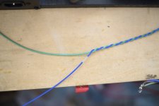
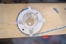
Anyway, to answer your above question about wiring dress, I assume you mean the AC to the socket, I'd probably do it something like in the pics.
Attachments
I haven't yet seen a definitive proof of effect of AC heater on IMD. That would be comparing IMD caused by AC heater to classic two-tone IMD test in the same amplifier.
The effect could be not specifically due to AC heater, but due to IMD distortion in an amplifier regardless of the mode of heating. This would be especially true for a SE topology with its relatively high harmonic distortion, since IMD and HD come together.
The effect could be not specifically due to AC heater, but due to IMD distortion in an amplifier regardless of the mode of heating. This would be especially true for a SE topology with its relatively high harmonic distortion, since IMD and HD come together.
If I do a trial of moving to AC, and just see what happens a couple of questions:
1. If I have over 10V AC - how is it best to reduce the voltage, a series power resistor?
2. Do I need to add some fixed resistors either side of the hum bucking pot to the wiper/cathode like the image attached?
Thanks!
1. If I have over 10V AC - how is it best to reduce the voltage, a series power resistor?
2. Do I need to add some fixed resistors either side of the hum bucking pot to the wiper/cathode like the image attached?
Thanks!
Attachments

This is a great design of the layout, fantastic - thanks!Well, now I'm starting to feel remorse for promoting the AC adventure in the face of wisdoms from my betters, BUT on the other hand your question is your question and if it's not erased by a night or two's good sleep there might be only one thing to do.
If I were going to do it however, I'd plan to take advantage of it being off the listening shelf for long enough to try some other things too. But that may all depend on what your power transformer can do and/or whether you are interested in making bigger changes. (Do you know what the power transformer is? Do you have the original schematic?)
Anyway, to answer your above question about wiring dress, I assume you mean the AC to the socket, I'd probably do it something like in the pics.
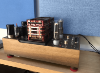
The amplifier is shown here and very large transformers, bog oak chassis and large plates of aluminium just add up.....it's about chest height on a shelf to keep 1000V well away from my 6 yr old 🙂Well, now I'm starting to feel remorse for promoting the AC adventure in the face of wisdoms from my betters, BUT on the other hand your question is your question and if it's not erased by a night or two's good sleep there might be only one thing to do.
If I were going to do it however, I'd plan to take advantage of it being off the listening shelf for long enough to try some other things too. But that may all depend on what your power transformer can do and/or whether you are interested in making bigger changes. (Do you know what the power transformer is? Do you have the original schematic?)
Anyway, to answer your above question about wiring dress, I assume you mean the AC to the socket, I'd probably do it something like in the pics.
Attachments
I assume the top blue is not connected to anything and the green is soldered here, and the blue is soldered at the bottom terminal?Well, now I'm starting to feel remorse for promoting the AC adventure in the face of wisdoms from my betters, BUT on the other hand your question is your question and if it's not erased by a night or two's good sleep there might be only one thing to do.
If I were going to do it however, I'd plan to take advantage of it being off the listening shelf for long enough to try some other things too. But that may all depend on what your power transformer can do and/or whether you are interested in making bigger changes. (Do you know what the power transformer is? Do you have the original schematic?)
Anyway, to answer your above question about wiring dress, I assume you mean the AC to the socket, I'd probably do it something like in the pics.
so the blue from bottom to top is just carrying voltage, but not current?
Could it also work by sort of running a 'ring' all the way around each valve socket, and retain the flow of current along all the twisted pairs?
sser2,
The proof is when you have the opportunity to use an HP 3585 spectrum analyzer, one of the 2 best analog spectrum analyzers that cover the audio frequency range (The Tektronix 7L5 analog spectrum analyzer was the other world class analog spectrum analyzer for audio).
Tests on various AC powered filaments, using spectrum analyzers does very easily, and very clearly show the intermodulation of:
2 times the power mains frequency on a single note, and all its natural harmonics, and multiple instruments too,
with their fundamentals and natural harmonics.
The key to the proof is that it is not 1 times the power mains frequency, it is 2 times the power mains frequency.
There are no 1 times fundamental power mains frequency upper and lower sidebands on the musical notes; instead they are 2 times the fundamental power mains frequency: upper and lower sidebands on all the musical notes, and on all the natural harmonics.
By natural harmonics, I mean the harmonics that are naturally produced by musical instruments.
They have harmonics already; no recording and no playback systems need to apply their own distortions, the harmonics are already there from the musical instruments themselves.
Changing the DHT filaments from AC powered to DC powered makes those sidebands go away.
That shows that the 2X power mains frequency was not caused by the ripple on the B+.
Need more proof, do it yourself and see.
Good luck coming within 100 miles of either an HP 3585 or a Tektronix 7L5 spectrum analyzer; but if you find a location that has one, be sure to bring your Left channel AC powered DHT, and your right channel DC powered DHT. Ha! . . . or, crossing the ocean to Japan Hi!
No microphones, no preamps, no amplifiers, no headphones, and no loudspeakers, even if they are perfect.
The instruments already have their own harmonics, but generally do not already have their own IMD products.
IMD requires 2 separate frequencies at the same time, in order to produce the 2nd order and the 3rd order IMD products.
Last edited:
Yes, but I do it this way for my own reasons and put it there after looking at a few pics of 845 amps with everything crammed together at very close quarters and thought yours might be the same. I made the photos with some off-cuts. Ordinarily I'd measure the length and cut first then pull the blue insulation so when finished the end of the blue insulated conductor is not exposed.I assume . . . . . .
You might be just as well off running twisted to one and from there single around to the other.
The 'ring' around the socket thing doesn't make any sense to me.
I started off my first reply not having seen the photo and assumed that if it was a commercial product it was probably ok with the AC filament. Perhaps even some sort of hum reduction in the overall circuit etc. It would be good to know exactly what the original circuit was.
I've seen a photo of that amp somewhere else before, years ago, the red colour on the transformers is unforgettable. No schematic or power transformer I.D. , etc. ?
I'm not expert enough to give more than basic generic opinions, I only know what I know and what I don't know and limit myself to building as well as I can within a fairly narrow framework. Your mention of your six year old turns on my caution light.
It would be nice if you could dig up and post either schematic, details, photo etc or a way to get to them through a website. (Where was that amp posted before anyway?)
My opinion doesn't change though. ie. Given that one's interest is not just the result of restlessness or boredom, experiments (that follow safety protocols) to answer a clear question are worth it, even if the result is to discover that you are better off with things the way they are.
If you go ahead with this, please post your results. Your experience helps everybody.
Thanks
- Home
- Amplifiers
- Tubes / Valves
- AC Heater for better Sound quality? Waste of time or worth a try