LEDs are shiny
you can use simple resistor divider , lower one blocked with nice elco
and most probably you'll not hear any difference vs. LEDs or your TL431
for me , most fun is having it shiny ......
you can use simple resistor divider , lower one blocked with nice elco
and most probably you'll not hear any difference vs. LEDs or your TL431
for me , most fun is having it shiny ......
Good day all!
I'm planning to build this amp approx. 60watt/ch.
I'll have 6-pair IRFP240/Ch like Aleph 60.
2x24VAC donuts 500W each dual mono.
Case is 5U 500mm HIFI2000.
some 2sj74s Idss 9-10mA
My questions are:
Do I have to piggyback the jfets?
Should I go for BDs instead of BCs bjt regarding the heat ?
Anything else I should be aware of?
Boards are homemade.
cheers
/Goffe
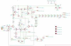
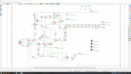
post #138 schematic
just one pair of input JFets , so no need for piggy-back
BC are OK for cascodes , but if you want , you can use BD
just one pair of input JFets , so no need for piggy-back
BC are OK for cascodes , but if you want , you can use BD
SMD PCB layout
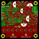
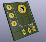
I wanted to try my hand on a compact layout for the front end "motherboard." I'm thinking about running the output transistors and source/gate resistors P2P and connecting to the motherboard at the labeled ports. The output transistors would have direct, heavy gauge power connections. The power on this board is only for the front end.
The board is 80 mm x 80 mm to keep costs down.
Comments?
The only connections to ground are from the input signal and U1. Is there any value in having a complete ground plane behind the remainder of the board?
Attachments
no need for ground plane
more , sorry , I'm sorta having mental block , when (not mine) pcbs are in case ... result of years of deciphering traces in service work
more , sorry , I'm sorta having mental block , when (not mine) pcbs are in case ... result of years of deciphering traces in service work
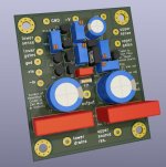
Progress
Tidied up the motherboard a bit, now it's roundabout 2.5 in x 3 in. Most of the resistors are on the backside for easier access. The mounting holes are connected to a chassis ground plane, which is kept separate from the signal ground, so I can preserve the star ground at the PSU.
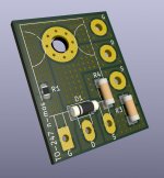
I'm thinking of taking a page out of XRK971's playbook and mounting the IRFP240s on compact boards with the gate stopper and an RC snubber circuit, and I've thrown the source resistors on there, too. I'm thinking that'll run some solid copper wire as "bus bars" to connect each bank of 4 back to the motherboard and to supply power from the appropriate rail. This offers a few advantages - much lower PCB cost, "neater" than dead-bug wiring, short trace lengths, and more forgiving of my rather poor hole-placement precision with a hand drill as compared to a large PCB with corner holes.
In the name of space - and current sharing - I currently have it set up with two paralleled 1% 0.68R MELF resistors rated at 1 W each. Since each resistor sees only about 100mW in the Spice sims (3 A bias over 4-deep output stage), it seems like I can forgo the standard 3W MOX part. I'm using similar 1W parts for the feedback current sense resistors, except 10 0.43R are paralleled to get the AC gain right about 40-42% like the Aleph J.
I fell down the rabbit hole of resistor distortion, so I'm using MELF 0207 for parts that will see >50 mW at any time and 0805 thin film for the rest (Susumu RG).
Tidied up the motherboard a bit, now it's roundabout 2.5 in x 3 in. Most of the resistors are on the backside for easier access. The mounting holes are connected to a chassis ground plane, which is kept separate from the signal ground, so I can preserve the star ground at the PSU.
I'm thinking of taking a page out of XRK971's playbook and mounting the IRFP240s on compact boards with the gate stopper and an RC snubber circuit, and I've thrown the source resistors on there, too. I'm thinking that'll run some solid copper wire as "bus bars" to connect each bank of 4 back to the motherboard and to supply power from the appropriate rail. This offers a few advantages - much lower PCB cost, "neater" than dead-bug wiring, short trace lengths, and more forgiving of my rather poor hole-placement precision with a hand drill as compared to a large PCB with corner holes.
In the name of space - and current sharing - I currently have it set up with two paralleled 1% 0.68R MELF resistors rated at 1 W each. Since each resistor sees only about 100mW in the Spice sims (3 A bias over 4-deep output stage), it seems like I can forgo the standard 3W MOX part. I'm using similar 1W parts for the feedback current sense resistors, except 10 0.43R are paralleled to get the AC gain right about 40-42% like the Aleph J.
I fell down the rabbit hole of resistor distortion, so I'm using MELF 0207 for parts that will see >50 mW at any time and 0805 thin film for the rest (Susumu RG).
Attachments

Last edited:
Can I used this front instead of aleph2I wanted to try my hand on a compact layout for the front end "motherboard." I'm thinking about running the output transistors and source/gate resistors P2P and connecting to the motherboard at the labeled ports. The output transistors would have direct, heavy gauge power connections. The power on this board is only for the front end.
The board is 80 mm x 80 mm to keep costs down.
Comments?
The only connections to ground are from the input signal and U1. Is there any value in having a complete ground plane behind the remainder of the board?
I was playing with my curve tracer and a SJEP120R100 part... and I realised that the SJEP has a negative temperature coefficient (current decreases when it heats up). Does that mean the SJEP does not need a source resistor for thermal compensation to prevent thermal runaway? Is it a good idea to skip the source resistor (R30 in post 618)? What would be the advantages and disadvantages of doing that?
well , you need some
I didn't tried without ..... though - it's easy enough for you to try
just power it up and set , observe DC offset and Iq in time and temperature domain and that's it
no brainer
I didn't tried without ..... though - it's easy enough for you to try
just power it up and set , observe DC offset and Iq in time and temperature domain and that's it
no brainer
Yes, that is exactly what that means 🙂
Check out the original F6. No source degeneration resistors.
They may be convenient for measuring Iq, however.
Check out the original F6. No source degeneration resistors.
They may be convenient for measuring Iq, however.
well , you need some
Uhm, ok. Sure I can just try and see what happens, but... The thing is that I don't understand why I need the source resistor. Can you switch on the light for me?
Yes, that is exactly what that means 🙂
Check out the original F6. No source degeneration resistors.
They may be convenient for measuring Iq, however.
Hmm, the F6 schematics I found have the source resistors in.
If I get you right, you are saying the source resistors only job is to avoid thermal runaway with output devices that have a positive tempco. Correct? Am I missing something?
Bias current (Iq) can be measured at the resistor of the Aleph current source (R29 in post 618).
mea culpa , was thinking much broader sentence but that's what I wrote ..... go figure
of course you got it right , with negative TempCo , you don't need source resistor
initial F6 ( SJEP in output) didn't had source resistors at all
later one , with Mosfets - made for enormous Greedy Boyz masses , logically have some resistors
of course you got it right , with negative TempCo , you don't need source resistor
initial F6 ( SJEP in output) didn't had source resistors at all
later one , with Mosfets - made for enormous Greedy Boyz masses , logically have some resistors
Speaking of measuring Iq, check these out: RMCJ2U00R05FS Johanson Dielectrics | Mouser
I’ve got a few to try. They are available in many values, including 0.1 Ohm.
I’ve got a few to try. They are available in many values, including 0.1 Ohm.
Can I used this front instead of aleph2
If you’re simply looking to build an Aleph in a modular approach, similar to how some build the Aleph 2 (for example, Pass Labs ALEPH-2 DIY amplifier KK-PCB layout), then this front end would likely work in a similar way. However, it’s set up for 30 V rails, not 45 V.
It’s also unbuilt and untested, and unless you’re willing to try to work through and troubleshoot it yourself, I’d recommend going with a proven design.
Ok, I put a jumper over the source resistor (R30). Works great with the SJEP120R100 outputs!
DC drift during warmup is about the same as before. Warmup drift is largely controlled by the Vbe temperature drift the the transistor in the Aleph current source, so unrelated to the outputs and source degeneration.
I can't say that the sound quality has changed in a big way. Certainly no night and day difference. Maybe there's a little bit more energy in the microdynamics (yeah, it's hard to describe). But maybe it's just my brain that thinks that there must have been some kind of improvement. Anyway, it's good and I'll just leave it that way. 😀

ZenMod, you seem to be a fan of the older Wima MKC caps as bypass for the electrolytics in the Aleph current source. As far as I can tell, those Wima MKCs are not available anymore. What would be a good replacement? Wima MKP?
- Home
- Amplifiers
- Pass Labs
- About possible Babelfish J interest