I wasn't referring to the mechanical issues, more to the fact that increasing R7 means that I get closer to the point where I can't zero the DC output value.
Anyway, I tried R7 = 500 Ohm. Result: range of bias current is about the same as before (can't go higher than 1.85 A). It is still possible to adjust DC output to zero, but it's close.
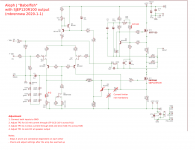
I thought the range of bias current adjustment is related to TP3 and the parts around it. Would it make sense to change the value of R24 maybe? Higher or lower?
Thanks for your help!
Anyway, I tried R7 = 500 Ohm. Result: range of bias current is about the same as before (can't go higher than 1.85 A). It is still possible to adjust DC output to zero, but it's close.
I thought the range of bias current adjustment is related to TP3 and the parts around it. Would it make sense to change the value of R24 maybe? Higher or lower?
Thanks for your help!
Last edited:
oh well , I understood that you're telling that SJEP side is bottleneck for increasing Iq ... while
now - just increase either value of R24 (120K) or replace TP4 with 100K
I know that you hate flipping pcb for doing that , but this time there is no other way
now - just increase either value of R24 (120K) or replace TP4 with 100K
I know that you hate flipping pcb for doing that , but this time there is no other way
just increase either value of R24 (120K)
Works!
I know that you hate flipping pcb for doing that , but this time there is no other way
Don't we all enjoy DIY!?
And then there is another issue: If I zero the DC at the speaker output after the amp has warmed up and then turn off the amp, let it cool down and turn it on again, the DC will be about 1V. This means the DC drift from cold to warm is about 1V. Is this because the IRF150 and the SJEP drift in different ways? If so: do I have to replace the IRF150 with another SJEP? Or is there another way?
it depends ..... best way is to put SS in both positions
second way is just ignore it , if you're not using Lowthers and if 1V state is short
if there is no abrupt behavior and prolonged in time , you can freely say that DC offset issues are overrated
second way is just ignore it , if you're not using Lowthers and if 1V state is short
if there is no abrupt behavior and prolonged in time , you can freely say that DC offset issues are overrated
it depends ..... best way is to put SS in both positions
If I'd replace the IRFP150 in the Aleph current source with a SJEP, would I have to change any parts (around the Aleph current source or elsewhere)?
Ok, I replaced the IRFP150 in the current source by SJEP120R100 parts. The DC drift during warmup is now a bit better, but not perfect. Once the amp has warmed up, the DC still drifts up and down by 0.1 V or so. I guess that's because every power FET has its own heatsink, and the heatsinks are not thermally coupled (at least not very much). Oh well, this is not a headphone amp and I am not a Lowther fan, so I might just leave it. The amp sounds great! 😀
Ok, I replaced the IRFP150 in the current source by SJEP120R100 parts. The DC drift during warmup is now a bit better...
Uhm, well, actually, I might have been a bit too quick with this.
Now that I am looking at the second channel I see that it starts at -1.6 V DC at the speaker output and slooooowly goes to zero after a few hours of warmup. My DC protection boards are not happy with this much DC, so I need to improve this.
To better understand what's going on I pointed my heatgun at different spots in/on the amp. Baking the heatsinks does change the DC offset a bit, but not by much (0.1 to 0.2 V maybe). The transistors of the input stage are much more sensitive. Simply touching one of the jFETs with my fingers for a few seconds changes the speaker DC by 0.3 V or so, and the heatgun will quickly make more than 1 or 2 V effect on the DC offset (I didn't dare to see where the limits are).
Maybe the jFETs heat up at different rates? I tried to thermally couple the input jFETs with a bit of goop and some heatshrink around it, so they are always at the same temperature. That didn't make a notable difference.
Any ideas what's going on? Suggestions?
(Don't tell me to remove the DC protection boards. I have done that with another amp, and I learned the hard way that this is a bad idea.)
problem with SS in exact circuit is mainly induced with lowish OLG - to accomodate lower Ugs of SS (vs. IRFP) , we need smaller impedance in input JFet drain , so OLG is decreased , thus ability of servo function of LTP itself
I believe later Papa's arrangement (J2) - using Mu follower on output , with surrounding resistances , is behaving better - more unison with lower part of circuit
you can try one thing - increase resistance of source resistor in Aleph CCS , instead of 0R27 use 0R33 or even 0R39 (beat me , is that regular value ? ) , reset for targeted Iq and observe
as I understand it - starting from negative DC offset and arriving at 0 , means positive TempCo behavior of Aleph CCS is main culprit
I believe later Papa's arrangement (J2) - using Mu follower on output , with surrounding resistances , is behaving better - more unison with lower part of circuit
you can try one thing - increase resistance of source resistor in Aleph CCS , instead of 0R27 use 0R33 or even 0R39 (beat me , is that regular value ?
) , reset for targeted Iq and observe as I understand it - starting from negative DC offset and arriving at 0 , means positive TempCo behavior of Aleph CCS is main culprit
Ok, I changed R29 from 0.27 Ohm to 0.38 Ohm (yes...) in one channel. Now I can't set the bias current to 2A anymore, highest is about 1.7A. This means the amp (or at least this channel) will not get as hot.
I started with a cold amp about 1h ago, and it's still warming up. However, the DC at the speaker output behaves pretty much the same as before, and I don't expect any surprises during the next hour of warmup. I looks like the higher value source resistor in the Aleph current source didn't help.
Is it possible that the input stage LTP goes out of balance during warmup?
increasing Iq ....... theoretically max is 0V65/0R38=1A7
it can be increased but only introducing pull down resistor for small bjt base , instead of pull-up resistor
anyway , 1A7 is decent Iq
now sole thing you can try is to increase source resistor for lower output device , resulting in higher needed resistance in input JFet drain , so increasing LTP servo functionality , regarding DC offset
another thing for that - short R6 and R15, to squeeze last ounce of gain from LTP
again , circuit is not optimized for SS outputs , if you tame it little more , that's it
Ok, will look into this.
(Why) don't you think it could be an imbalance in the input stage LTP?
(Why) don't you think it could be an imbalance in the input stage LTP?
Problem solved!
It was a long night, with an unexpected end.
After changing the source resistors in the output stage didn’t help anything, I felt that the DC drift problem might not be in the output stage after all. To convince myself, I reverted one channel to the “standard” configuration with two IRFP150 transistors and all part values as in the original schematic. The drift was pretty much the same. This was my “proof” that the issue is not related to the outputs, and I got more and more convinced that the JFETs in the input LTP were not good. I decided to replace them with known good and well matched LSJ74 parts from the diyAudio store. I took the amp back to the workshop for the surgery, and once it was done I hooked it up to the lab PSU in the workshop. Rock steady DC, drift less than 0.02 V from cold to warm! Great!
But… in the listening room, the DC drift was back, as bad as ever. Dammit! How is this possible!?
The only difference between the workshop and the listening room was the external power supply. In the listening room I use an external SMPS that provides the +/- 24 VDC to the CLC filter in the amp chassis. Once I took a closer look at the power supply output voltages I realised that the rail voltages I got from the SMPS were not perfectly symmetric.
A simple twist of the voltage adustment pot at the SMPS was all it took to stop the nightmare...
Thanks for all the support here! Happy New Year to everyone!

For a point-to-point build, I didn't want to mess with the SMD jfet, and I wasn't confident in selecting an alternative inexpensive jfet with equivalent noise performance (which seemed important, but I could be wrong). I recalled that the BA-2 output stage uses a TL431 as a voltage reference, so I wanted to see how it'd work in place of the LEDs + jfet CCS.
I deleted the LED string and the jfet CCS and connected the voltage reference as shown on the right, where R61 just drops to the -30 V rail.
I picked some mostly arbitrary resistor values (R59 <10k; R60 reasonably high) to give the same -12.625 V reference for the cascode Q1 and Q2, and it seems to perform pretty well and reject power rail ripple better than the original (although there's certainly no practical difference). The plotted voltage is taken between R19 and R20, or the anode of the TL431.
Is there an advantage to sticking with the original reference with the LEDs and CCS? Are there problems with this substitution that I should consider?
Attachments

Last edited:
- Home
- Amplifiers
- Pass Labs
- About possible Babelfish J interest