now when I did saw your build ...... never try to polish an amplifier when you have it built in so exploded fashion 
been there, done that ....... countless hours of gilding the Lilly thrown in basket, when I put everything nice and tidy; again countless hours to tame it, just to be back to basics and pull just few tricks from hat to get perfect behaving
when you have final parts there, with proper short/optimized wires, then worry about falling and leading edges
now when I did saw your build ...... never try to polish an amplifier when you have it built in so exploded fashion
been there, done that .......
Oh, sure, the final build may behave differently. I am just trying g to learn and understand what's going on in the prototype.
Hi ZenMod
I was experimenting with my curve tracer, and I needed a low-current part to test a new idea I had. I found a little bag on my desk with the J271 parts that came with your Babelfish-J package, so I put them in the tracer. However, the curves didn't look right for a J271. For comparison I also traced the LSJ74 I bought from the diyAudio Store, and those curves look perfectly okay (see attached figures). I wonder what's up with your "J271". Where did you get them?
I was experimenting with my curve tracer, and I needed a low-current part to test a new idea I had. I found a little bag on my desk with the J271 parts that came with your Babelfish-J package, so I put them in the tracer. However, the curves didn't look right for a J271. For comparison I also traced the LSJ74 I bought from the diyAudio Store, and those curves look perfectly okay (see attached figures). I wonder what's up with your "J271". Where did you get them?
Attachments
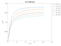
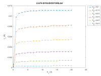
nothing wrong that I can see at these graphs
these are exactly J271, not having anything as number in front
so , there is no real comparison with LSJ or 2SJ
though , they are working nice in Aleph J FE, not exactly refinement as original 2SJ or LSJ, but very close
they're bought in quantity, along with J309 , 9 yrs ago - either at Digikey or Mouser, when I was at BAF
Whoops, sorry, my bad. Brain malfunction. I sort of thought that 2SJ74 = LSJ74 = J271. Oh well...
Greetings from a newbie. After reading this forum for the past 2 weeks, I am only a little closer to deciding what amp to build, but have sort of settled here. I have never built one, and probably won't ever again, I tend to switch hobbies a lot. Point being, I wanted something sort of endgame, with the power to drive whatever speakers in whatever reasonable room, and it seems this has a special harmonic signature worth exploring.
I'm wondering if there might be significant sonic benefit from trying 2 dual mono Babelfish J, to bi-amp. Having never experienced it, it's hard to judge what the improvement might be. It's either that or going normal monoblocks. Not planning on separate PSU chassis, plenty seem to get the PSU in the main chassis with zero noise.
Thank you to all for your work and time. I will have lots of questions once I start, but will make a new thread to not clutter this one.
biamp ...... it really depends of speaker used
if you already have them , try with amp you already have, using mono signal to two channels to mono biamp one box
it'll take some time to accomodate brain to mono sound, but you'll manage and you'll hear any significant difference
then you'll have your answer, got in best way
if you already have them , try with amp you already have, using mono signal to two channels to mono biamp one box
it'll take some time to accomodate brain to mono sound, but you'll manage and you'll hear any significant difference
then you'll have your answer, got in best way
I have a pair of these excellent boards - just working out the details of how to implement.
Power from one device "per quadrant" is probably OK, maxed out. But it's really pushing the heatsink, being that there are only 2 points of heat input per sink.
I'd probably be better off with 2 devices per quadrant. I don't have the breakout board. Could I point-to-point with necessary couple of resistors? Would it be best to point-to-point both devices? Or use one on the PCB and one point-to-point. (OCD would mean I would much rather point to point both in this case to keep it all equal...)
I did use term "per quadrant" only when thinking/speaking about bridged- X amps ( so there are really two right and two left quadrants)
so you got me confused there
care to post some graphic illustration of what you're talking about?
so you got me confused there
care to post some graphic illustration of what you're talking about?
A scrappier sketch is not possible 🙂. But I hope it makes sense. Left Channel just used as example. Both would be the same

so, now refrain your question, please, taking in account what part of explanation is for electrical side of circuit, and what part of explanation is for physical layout of the same
I see that you're thinking in "quadrant" terms about physical layout and I'm guessing that you want to use 2 pairs of mosfets per channel ( mounting them in quad way around pcb) but I need to be sure what you're thinking of, to give proper reply
I see that you're thinking in "quadrant" terms about physical layout and I'm guessing that you want to use 2 pairs of mosfets per channel ( mounting them in quad way around pcb) but I need to be sure what you're thinking of, to give proper reply
Sorry, yes. I'm thinking about using 2 IRFPs in parallel, where the "default" boards just provide option for a single MOSFET.
in that case, you're thinking good
omit source and gate resistors on pcb, each mosfet is having these ditto, take care of having proper number/value of output sense resistors on pcb
rule of thumb - if you have sum of 4 source resistors ( 4 mosfets) then same number (4) of same value resistors need to be in output sense group
omit source and gate resistors on pcb, each mosfet is having these ditto, take care of having proper number/value of output sense resistors on pcb
rule of thumb - if you have sum of 4 source resistors ( 4 mosfets) then same number (4) of same value resistors need to be in output sense group
Excellent - thank you. And I had missed that I would need to double up the output sense resistors.
Presumably I only want to connect a single MOSFET source directly back to R25 as in this schematic? Otherwise it'd be strapping the sources directly together.

Presumably I only want to connect a single MOSFET source directly back to R25 as in this schematic? Otherwise it'd be strapping the sources directly together.
Hello hello 🙂
Here is my Babelfish J graciously provided by ZM himself
I am Papa fan and ZM fan so eagerly awaited to see results of this "collab"

Less than ideally tidy, at some point i had enough and just wanted to finish it.
We have the SMPS psu -> 50kuF bank -> juma style mosfet cap mult for both rails for both channels -> B-J
Bias current first tried with 1.8A, heatsinks can hold normal but power supply struggles (a lot) so cranked down all the way to 1.2A.
I built it even before, but i was just testing and trying to iron out bugs.
Overall board is decently laid out, except maybe the 2 ground quick disconnects RIGHT in front of the non-standard 3 pin terminal. That one i just cant understand why it wasnt moved 5mm to the side. Makes installation difficult, output current return loop area is large (since its on the opposite side of the board to the output), and the other connector doesnt even have the hole for the other leg (you can see on my pcb just sticking outside the pcb on the top). Maybe i am missing something, dont take it the wrong way i dont want to ruffle feathers just being honest and discussing.
Anyway something seems wrong, sound is very ehh to the point where i somehow dont think this is what was intended, even at 0.5W.
I know it should have tube characteristic, but seems like sine wave has more harmonic than fundamental, maybe a bit exxageration but it is grainy. And it is same on both channels, so i assume it is not individual component damage. Since A3 sounded great with same psu and everything, i assume isnt that either.
Here are all the changes i ended up doing:
output mosfets irfp250M (instead of 150)
source resistors 0.25ohm
output resistors 0.15ohm (3x0.47) original was 0.135 (2x0.27)
LED's bypassed by 9.1v zener, cause i dont like lights at night. Sim shows should be ok.
Gate resistor 200 instead of 180.
Used BC550B BC560B instead of x46 x56 (lower noise). Q5 protection is 546C.
No 1nf C12.
R1 bridged, only TP3 used to Iq setting (it was waay too much).
-IN and GND bridged, since i only have SE input.
Power rails only +-18V. Dropped because of cap mult and because PSU was struggling. I increased later briefly to test to 24V, no difference really.
I only listen to <1W (maybe 2vpp), since im nearfield, and even then it is noticable something is not right.
Also i have flat foil cable. Capacitance pretty high, and inductance is very low, but didnt oscillate with aleph mini or Class D's. I assume BJ is stable too.
NOTE that this does not represent the true amp as builder intended, as i made some changes (should be benign but still). So take this post with a grain of salt, real amp should be good.
Attached schematic of my board version, and simulation file with all my changes (sorry it is ugly).
Here is my Babelfish J graciously provided by ZM himself
I am Papa fan and ZM fan so eagerly awaited to see results of this "collab"
Less than ideally tidy, at some point i had enough and just wanted to finish it.
We have the SMPS psu -> 50kuF bank -> juma style mosfet cap mult for both rails for both channels -> B-J
Bias current first tried with 1.8A, heatsinks can hold normal but power supply struggles (a lot) so cranked down all the way to 1.2A.
I built it even before, but i was just testing and trying to iron out bugs.
Overall board is decently laid out, except maybe the 2 ground quick disconnects RIGHT in front of the non-standard 3 pin terminal. That one i just cant understand why it wasnt moved 5mm to the side. Makes installation difficult, output current return loop area is large (since its on the opposite side of the board to the output), and the other connector doesnt even have the hole for the other leg (you can see on my pcb just sticking outside the pcb on the top). Maybe i am missing something, dont take it the wrong way i dont want to ruffle feathers just being honest and discussing.
Anyway something seems wrong, sound is very ehh to the point where i somehow dont think this is what was intended, even at 0.5W.
I know it should have tube characteristic, but seems like sine wave has more harmonic than fundamental, maybe a bit exxageration but it is grainy. And it is same on both channels, so i assume it is not individual component damage. Since A3 sounded great with same psu and everything, i assume isnt that either.
Here are all the changes i ended up doing:
output mosfets irfp250M (instead of 150)
source resistors 0.25ohm
output resistors 0.15ohm (3x0.47) original was 0.135 (2x0.27)
LED's bypassed by 9.1v zener, cause i dont like lights at night. Sim shows should be ok.
Gate resistor 200 instead of 180.
Used BC550B BC560B instead of x46 x56 (lower noise). Q5 protection is 546C.
No 1nf C12.
R1 bridged, only TP3 used to Iq setting (it was waay too much).
-IN and GND bridged, since i only have SE input.
Power rails only +-18V. Dropped because of cap mult and because PSU was struggling. I increased later briefly to test to 24V, no difference really.
I only listen to <1W (maybe 2vpp), since im nearfield, and even then it is noticable something is not right.
Also i have flat foil cable. Capacitance pretty high, and inductance is very low, but didnt oscillate with aleph mini or Class D's. I assume BJ is stable too.
NOTE that this does not represent the true amp as builder intended, as i made some changes (should be benign but still). So take this post with a grain of salt, real amp should be good.
Attached schematic of my board version, and simulation file with all my changes (sorry it is ugly).
Attachments

can you edit your schematic and put DC vaues in most important positions?
you know- cascode base voltages, voltages across R10 and source resistors .... etc.
btw, quick connects were not intended at all - I don't like them and I don't make my pcbs adequate for same
you know- cascode base voltages, voltages across R10 and source resistors .... etc.
btw, quick connects were not intended at all - I don't like them and I don't make my pcbs adequate for same
Yes, but it sounds like its gonna be a not so easy troubleshoot, so i'd have to find another time block to pick it up. Thank you for your help offer.can you edit your schematic and put DC vaues in most important positions?
you know- cascode base voltages, voltages across R10 and source resistors .... etc.
For source resistors i know at least, ~0.3V on 0.25ohm, thats how i know Iq is 1.2A.
Ooh i see, probably a 3 leg terminal block? Ok, fair enoughbtw, quick connects were not intended at all - I don't like them and I don't make my pcbs adequate for same
no blocks, just soldering
I mean - if you can squeeze them in, do it
I didn't even think of them
regarding Iq, 1A2 is on lowish side
will take a look later at IRFP250 datasheet; primarily interested in interelectrode capacitances...... comparing to IRFP150
if you don't have heatsink capacity for more juice, think of using IRFP240

Heatsink is ok, about 55-60C at mosfets on 1.8A. Just PSU was reaching 80-90C and not very happy with it. I need to look into getting a better one eventually... yes i suppose higher quiescent would help but im not sure by how much, and im definitely not leaving class A at <1W listening.regarding Iq, 1A2 is on lowish side
will take a look later at IRFP250 datasheet; primarily interested in interelectrode capacitances...... comparing to IRFP150
if you don't have heatsink capacity for more juice, think of using IRFP240
Credit: Firstwatt
Maybe i should switch to 240s. 250s worked great on Aleph 3 mini, also about 20V-ish and topology is not that different, and that's what i had already so i didn't think too much about it at the time..
- Home
- Amplifiers
- Pass Labs
- About possible Babelfish J interest