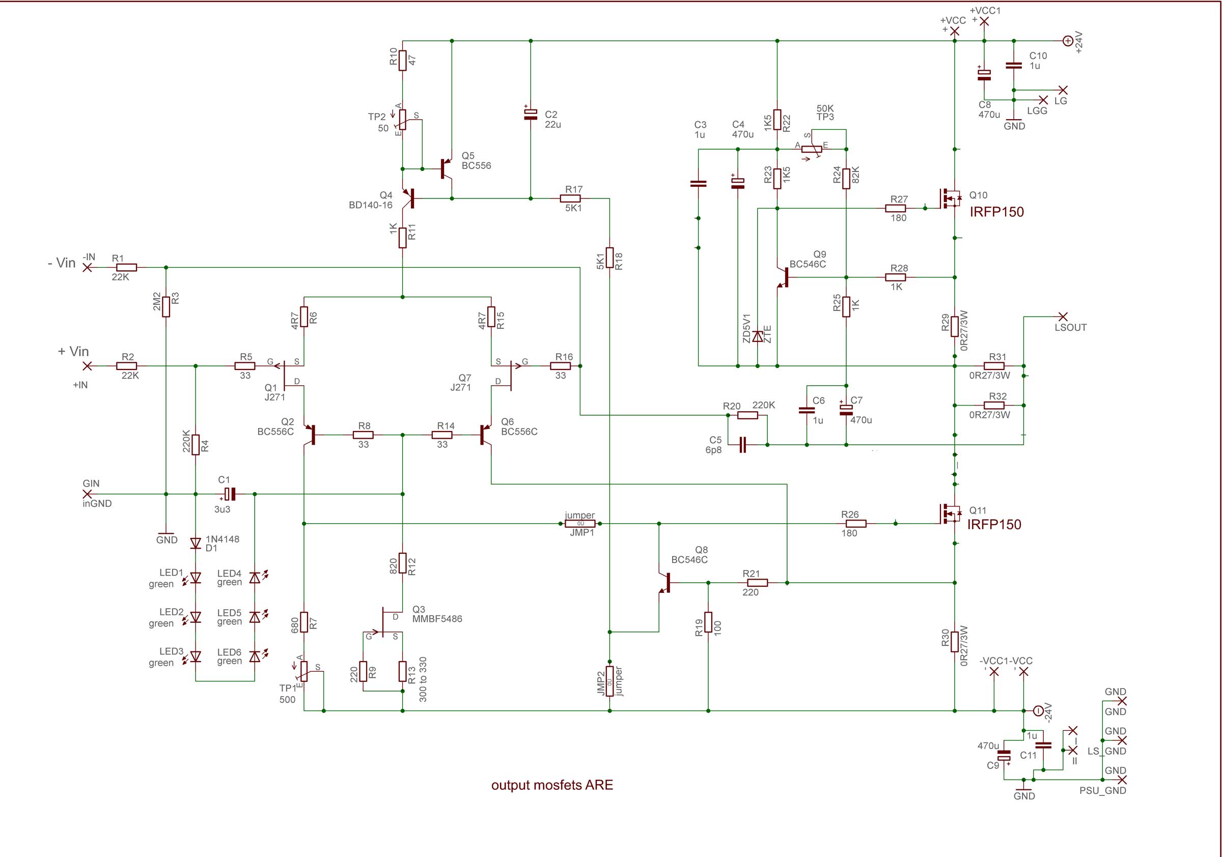
final schematic for just base pcb iteration and parts placement pictures
What is the max bias current for a single transistor pair?
What are the dimensions of the board?
How can I (still) get a board?
IRFP150 - standard rail (22V5dc , resulting from 18Vac secondary) , will work with Iq of 2A for eons , if properly cooled
higher rails , for more power , demands more output pairs (thus Daughter boards) and decrease of Iq per vertical pair , to limit max sane dissipation per device at max 45W
base pcb is shown with dimensions in post #1
it is slightly changed later in development , but nothing substantial
that board you can get if you contact me , first reading Trade thread , link of which is also in post #1
IRFP150 - standard rail (22V5dc , resulting from 18Vac secondary) , will work with Iq of 2A for eons , if properly cooled
Sounds good to me. Should the transistors pairs go to the same heatsink (for thermal tracking), or can they each have their own heatsink? I am thinking of doing a Pass Aleph style build with four heatsinks on each side of the chassis. Then I'd have 2 x 2 IRFP150 for a stereo amplifier, so each IRFP150 could go to it's own heatsink.
separate heatsinks - yes, already done
heatsinks being parts of same enclosure (temperature container) - that's enough for proper thermal tracking
heatsinks being parts of same enclosure (temperature container) - that's enough for proper thermal tracking
If I had some SJEP120R100 and wanted to use these in the "lower" MOSFET position, would this work with the Babelfish J? Would I need to change anything? Different part values anywhere?
ref. to enclosed sch. just value of R7 , decreasing or shortie
also , you can make life little easier - put shortie instead of TP2 , change R10 to 68R
also , you can make life little easier - put shortie instead of TP2 , change R10 to 68R
ref. to enclosed sch. just value of R7 , decreasing or shortie
Thanks! What would be a good value for the bias voltage at the gate of the SJEP120R100?
also , you can make life little easier - put shortie instead of TP2 , change R10 to 68R
Ok -- but is this related to the SJEP120R100 idea, or just to make things easier in general?
What would be your guess for the max. bias current possible with a single SJEP120R100 with +/-23 VDC rail voltage and a rather large heatsink?
Ok, so about 2 A in my case. How much further can I push my luck? Any chance it will survive at 55 or 60 Watt?IRFP150 up, SJEP down , count on 45W of heat per device , when properly cooled

final schematic for just base pcb iteration and parts placement pictures
Sorry for nagging, but the boards I received seem to be from a later revision. They have additional resistors R33, R34, R35 and R36. As far as I can tell, there are not other changes, but I am not sure.
I believe all I have to do is to leave R33, R34, R35 and R36 empty and not worry about anything else. However, I am not sure if I missed anything, so it would be cool if someone could confirm.
will answer tomorrow , as soon I catch some sleep
BAF was great , even if exhausting 🙂
Did you sober up? 😀
read and observe schematic little more
goal is to understand it
if you have , say, one 0R27 per output mosfet source, and you have 2 output mosfets, then you have 2pcs of 0R27 paralleled in output current sense series group
if you have 2 pairs of output mosfet , then there are 4pcs of 0R27 paralleled in output current sense series group
if you have 3 pairs of output mosfet , then there are 6pcs of 0R27 paralleled in output current sense series group
what's there , one can't understand?
if you have , say, one 0R27 per output mosfet ... if you have 2 pairs ... if you have 3 pairs ... what's there , one can't understand?
Hi ZM, sure, I understand the purpose of those additional resistors. But the core of my question was something else:
...the boards I received seem to be from a later revision. They have additional resistors R33, R34, R35 and R36. As far as I can tell, there are not other changes, but I am not sure.
You indicated that post #138 has the final schematic. That's obviously not the case, and I wondered if the changes in the board I received are only related to R33, R34, R35 and R36, or if there are any other changes. Can you confirm? Maybe you could simply post the correct schematic?
- Home
- Amplifiers
- Pass Labs
- About possible Babelfish J interest