Spent the day over a hot stove cooking transistors!
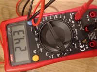
Well actually a waffle maker. After a couple hours dialing in the perfect setting I started testing. Tested at about 70 degrees Celsius, according to my multimeter at the bolting plate, my laser thermometer was showing 54 degrees Celsius at the back of the chip during each test.
I tested per Zen Mod’s drawing, and held the test for 60 seconds each chip. I kept 6-7 chips cooking on the heatsink to be up to temp by the time they were tested. I tested non stop without any adjustments or turning anything off or on, so results should be consistent.
So out of 125 chips here are the results;
4.04, 1
4.05, 8
4.06, 13
4.07, 7
4.08, 9
409, 6
4.10, 4
4.11, 8
4.12, 6
4.13, 7
4.14, 8
4.15, 17
4.16, 12
4.17, 10
4.18, 4
4.19, 1
4.20, 1
4.21, 2
4.22, 1
So looks like I’ll use 12 pcs of 4.15 for one amp and 4 pcs of 4.16 for the other amp.
Any other advice or did I miss anything?
you remember that you need to have matched mosfets "just" in same group , meaning group on positive rail is all mosfets matched , and group in negative rail is all mosfets matched
no need to match upper with lower ones
without going muuuuuucho back in thread , I can't grasp how many of them you have in output
certainly 3 (one daughter board) and even maybe 3+3=6 , per polarity
however , from your words in previous post (12 for one amp) , it's 6 up and 6 down .... so matched sextets it is
but - chill up , those being apart for 10mV are close enough .... so , you can use , for instance, those of 4.15 mixed with those of 4.16
so , plenty combinations to choose from
you remember that you need to have matched mosfets "just" in same group , meaning group on positive rail is all mosfets matched , and group in negative rail is all mosfets matched
no need to match upper with lower ones
without going muuuuuucho back in thread , I can't grasp how many of them you have in output
certainly 3 (one daughter board) and even maybe 3+3=6 , per polarity
however , from your words in previous post (12 for one amp) , it's 6 up and 6 down .... so matched sextets it is
but - chill up , those being apart for 10mV are close enough .... so , you can use , for instance, those of 4.15 mixed with those of 4.16
so , plenty combinations to choose from
Thanks for the reply!
Yes in build I have 6 up and 6 down, each amp.
So I have enough of the 4.15’s for one amp and enough 4.16’s for the other.
Since I have enough, I thought I would run them through another test. So same test as before but at 30v. I did just the 4.15’s so far. Thought that this would further let me pick how to match in 3’s. This is how they faired;
3.963
3.972
3.974
3.974
3.976
3.979
3.982
3.982
3.984
3.984
3.985
3.986
3.988
3.988
3.995
3.997
3.998
Do you think 30v is a good test for my build? I have 38v transformers, 48v rails, .47 ohm sense resistors, 1 ohm source resistors.
Quick question, what's the best thermally conductive insulator to use between mosfet and heatsink? I've found a lot of topics about this in the forums but no clear answer.
Any alternatives using something that would be available locally? Mica pads/thermal grease? Silicon pads?
I'm quite close to complete the wiring and assemble everything up. Was just curious on the powering up step. What is the standard procedure?
shorted inputs , no load on output
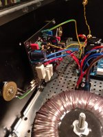
one DVM on output to gnd , for output offset
second DVM across source resistor of , say , lower mosfet
third DVM ready for any other measurement
did you checked PSU , prior to connecting it to amp pcbs ?
common psu for both channels , or dual mono ?
one DVM on output to gnd , for output offset
second DVM across source resistor of , say , lower mosfet
third DVM ready for any other measurement
did you checked PSU , prior to connecting it to amp pcbs ?
common psu for both channels , or dual mono ?
if you have just RCA input , be sure that you solder shortie ( piece of wire) between negative input and GND on pcb
shorted input means - take cheap RCA jack , solder shortie between GND and hot , and shove it in RCA in of amp
that's preventing crocodile getting in , if you leave input unguarded

shorted input means - take cheap RCA jack , solder shortie between GND and hot , and shove it in RCA in of amp
that's preventing crocodile getting in , if you leave input unguarded
should i use wire as thick as possible between mosfet and amp pcb? planning to use 1.5mm
this is in case not connecting it directly to the board..
this is in case not connecting it directly to the board..
D and S
Gate can be connected with tiny one
if wires longer than , say , 6 or 7cm , think about moving gate resistors to mosfet gates , series with wire (heatshrink )
then put shorties on pcbs , instead of gate resistors
Gate can be connected with tiny one
if wires longer than , say , 6 or 7cm , think about moving gate resistors to mosfet gates , series with wire (heatshrink )
then put shorties on pcbs , instead of gate resistors
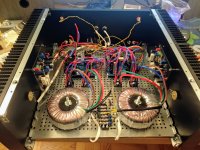
Huh.. finally got everything connected ! Please remind me next time NOT to use mica pads + goop, it's quite a mess when attaching...
Anyways, before turning the power on - anything I should be aware of? As per instructions - planning to track voltage across R11, R29 and output node to get the right measurement adjusting the TP2, TP3 and TP1. Should I start with closed lid to get the measurements at the running temperature?
Anyways, before turning the power on - anything I should be aware of? As per instructions - planning to track voltage across R11, R29 and output node to get the right measurement adjusting the TP2, TP3 and TP1. Should I start with closed lid to get the measurements at the running temperature?
Attachments
- Home
- Amplifiers
- Pass Labs
- About possible Babelfish J interest