ZM, could you get these as well, 1st one most importantly...
1) In case using only base PCB, I should only connect AD-AS, instead of N1-N2 right?
2) Is there a good reason placing transformers in front of the case and wiring through the bottom baseplate? Looks easier to have them in the back with less wiring.
ignore AD and AS
you can also ignore N1 and N2
or use either one to solder fat wire bridge
N1 and N2 are exactly for bridge , because when you're using multiple output pairs , there is significant current flowing through copper traces
while AD means All Drains (drain side of all mosfets in lower group) , and AS means All Sources (source side of all mosfets in upper group) , when using multiple outputs
with just one pair of outputs simply ignore these pads
I'm always routing (just) mains wires (going from IEC on back to xformers in front)bellow base plate ; that way base plate is also serving as shield for mains wires
when I'm using other case , without base plate , I'm always screening mains cable , going from IEC on back side to xformer in front
Got slightly distracted from the project for a while 🙂
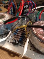
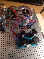
Anyways, started wiring the whole thing, wanted to check if I'm on the right track... any suggestions would be highly appreciated 🙂
White double flat wires - mains coming from power inlet module
Yellow wires - mains input to transformer
Added 2 CL60 via terminal block - hate the wire mess there :/
Blue/brown and red/green pairs - secondaries into bridge rectifier
Doubled DC wires from bridge rectifier.. red-positive, blue-negative
Attachments
Haven't done cuts yet to back plate, but was planning to have IEC, switch and fuse in single module. If fuse have to go per transformer I'll switch to separate IEC, switch and two fuse holders.. I am planning on going with slow blow fuse ~3A, does that sound right?IEC , switch and fuse holders (one per Donut) ?
made bulb tester yet?
Not yet, but I will definitely have one knowing that something might go wrong 🙂 Assuming you're talking about one on mains.
one IEC , one switch , then two fuse holders (one per Donut)
no need for separate IEC and switches
unless you insist ...... 🙂
no need for separate IEC and switches
unless you insist ...... 🙂
would be kind of cool though to have two IEC with separate switches for each channel 🙂 but no, I meant 'separate' as non-monolith IEC/fuse/switch module
sooo, 3A slow blow fuse is ok? ceramic better than glass?
sooo, 3A slow blow fuse is ok? ceramic better than glass?
250VA/230Vac = 1A08
say that slow blow 1A25 or 1A5 or 1A6 will do the job
so , start with whatever you can find easier , prefix is T , as T1.6A
say that slow blow 1A25 or 1A5 or 1A6 will do the job
so , start with whatever you can find easier , prefix is T , as T1.6A
just two things you can do better:
-match mosfets (upper group matched , lower group matched , no need of matching upper with lower group) ....... but that was Conditio Sine Qua Non from first train station ........ 🙂
-fiddle with Aleph AC gain to please your ears
For some reason I didn’t pick up that the mosfets had to be matched, my bad! I did use all from one sleeve so maybe not too far off.
I ordered another 150 pcs (IRFP240) to match up and ordered matched source resistors too.
My question is what voltage and what size resistor should I use for my build? In Nelson Pass’s 1993 article about matching (http://www.firstwatt.com/pdf/art_matching.pdf) he uses 15v with a 560 ohm resistor for VGS in the 4-4.6v range.
I set up a little test rig and using those voltages, resistor, and 20mA current I am getting results in the 2.7-2.9 range on the first few I tested this way.
For final testing I am planning on heating them up to operating temperature too.
Can you comment? Thanks

have PSU able to deliver 1A or more , from 15V to , say 25V ?
have some power resistors , those golden ones , 25 to 50W ....... 4R or 8R ?
have some power resistors , those golden ones , 25 to 50W ....... 4R or 8R ?
Yes to both power supply and I have both 4 and 8 ohm load resistorshave PSU able to deliver 1A or more , from 15V to , say 25V ?
have some power resistors , those golden ones , 25 to 50W ....... 4R or 8R ?
Yes to both power supply and I have both 4 and 8 ohm load resistors
started drawing something in spice , then remembered that I must have something from before
anyway
Attachments
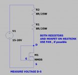
started drawing something in spice , then remembered that I must have something from before
anyway
Thanks for the reply and drawing!
My power supply can go to 30v and 5amps.
The resistors I have are 120w. Put into series for a 16ohm load. Bolted to a heatsink, no added heat.
I just tested one at 20v, this setup drew .53amps, and VGS was 11.48, and slowly dropping.
Is this a good process, except maybe to heat them up to operating temperature first?
Thanks
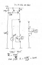
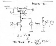
here's fishing apparatus for ya:
http://www.firstwatt.com/pdf/art_matching.pdf
http://www.firstwatt.com/pdf/art_mos_test.pdf
and few older back o' napkins
http://www.firstwatt.com/pdf/art_matching.pdf
http://www.firstwatt.com/pdf/art_mos_test.pdf
and few older back o' napkins
Attachments
here's fishing apparatus for ya:
http://www.firstwatt.com/pdf/art_matching.pdf
http://www.firstwatt.com/pdf/art_mos_test.pdf
and few older back o' napkins
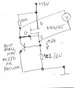
I think your playing with me, you know this is over my head!
But I tried to follow this;

With the exception for the BC 550 (BJT, NPN) I only had a C4793. And for the 1R2/3W I used a 1R/5W.
Don’t laugh at my test bed, but here you can see the volts, amp draw, and VGS.

I tested 3 at room temp, volts and amp draw stayed consistent, VGS was 4.29 and 4.40 on the other two.
Work? Thanks in advance.
- Home
- Amplifiers
- Pass Labs
- About possible Babelfish J interest