lol, i did search, looks much the same as on your build 🙂 it's just that the difference between them seems negligible, was wondering if there's a chance of damaging the resistor if the wattage is bit smaller..
Most of these resistors are very conservatively rated. Unless a position calling for 1 watt, 3 watt, 5 watt and so on 1/4 is usually adequate, sometimes 1/8 watt. But for better sleep....My F5 boards from Peter Daniels required standing up soldier style (which I did) anything over 1/8 watt.
Russellc
Russellc
Last edited:
@Russel, thanks for the tip, will take it into account when soldering resistors.
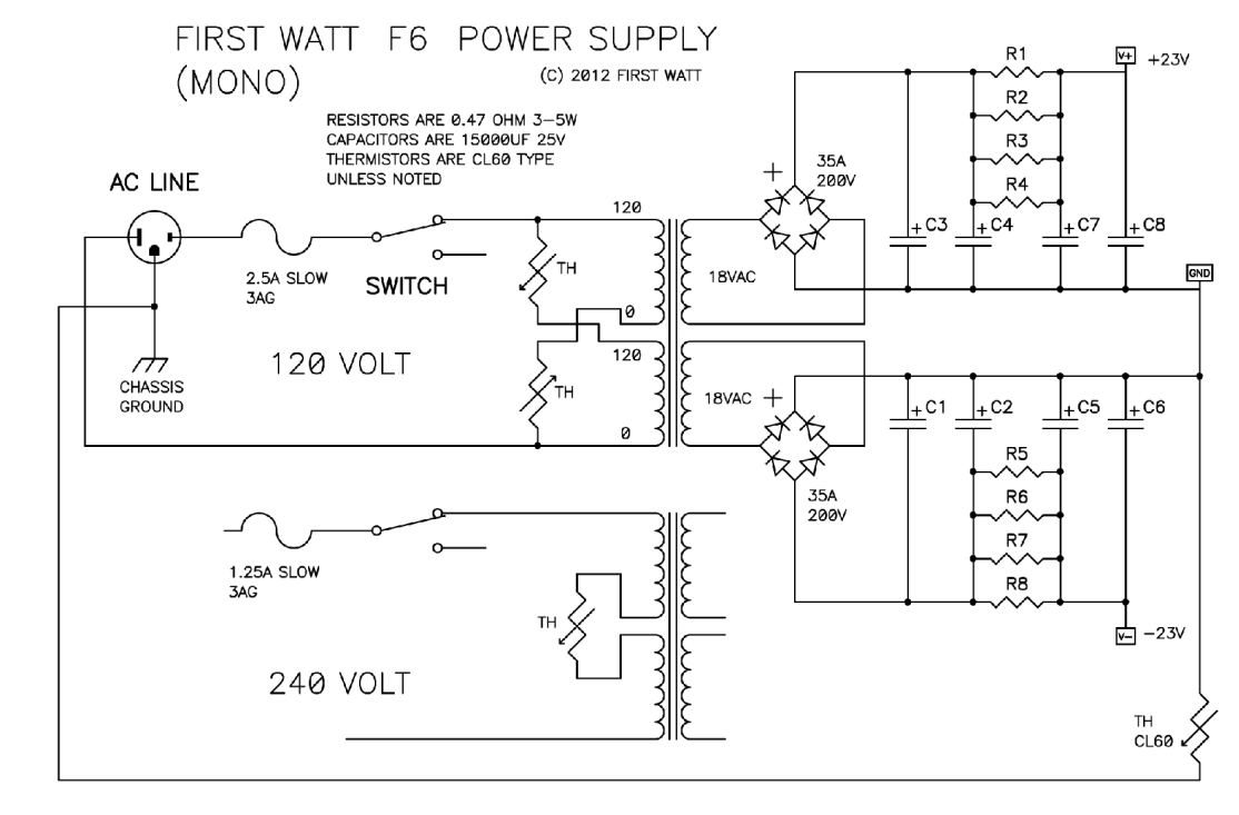
Hey ZM, any news on psu schematics ?? 😀
Anyways, started stuffing the board and noticed small mismatch between Q5 transistors you've sent (BC546) and labels that are attached (BC556) - see photo. Let me know if it still OK to go with it.
Hey ZM, any news on psu schematics ?? 😀
Anyways, started stuffing the board and noticed small mismatch between Q5 transistors you've sent (BC546) and labels that are attached (BC556) - see photo. Let me know if it still OK to go with it.
Attachments
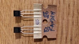
my bad
anyway - these are non-matched - random , so use anything you have in drawer
regarding schematic of PSU , same applies as in Babelfish M25, SissySIT - general building tips and tricks , post #113
anyway - these are non-matched - random , so use anything you have in drawer
regarding schematic of PSU , same applies as in Babelfish M25, SissySIT - general building tips and tricks , post #113
No problem, found couple BC556 options, one - 80V 0.2A 0.5W, other - 65V 0.1A 0.5W. Guess both would work.
BTW, I had to pick different values for few resistors (due to unavailability), am I ok staying in 10% threshold?
BTW, I had to pick different values for few resistors (due to unavailability), am I ok staying in 10% threshold?
R17-18 - 5.1k got 5.6kwhich ones?
R22-23 - 1.5r got 1.6r
well, the availability might never be there 😀 anyways, i got it in lower wattage so might play around by connecting in parallel or in series to get it right if it's important to have exact valueswhy hurry?
5K6 instead of 5K1 ok , and even better putting one 5K6 and another 4K7
R22, R23 - these are 1K5 , not 1R5
you can use 1K6
R22, R23 - these are 1K5 , not 1R5
you can use 1K6
R22, R23 - these are 1K5 , not 1R5
I should probably do this in the morning... It is 1K5 in the list I have.
Thanks for checking anyways, I should be good to go with what I have then.
Got few questions on components:
1) TP2 trimmer resistor in BOM is 50ohm, I got 20ohm version - is it sufficient?
2) C5 - no silver mica can be found here.. do you recommend using regular multi-layer ceramic or SMD on custom legs?
1) TP2 trimmer resistor in BOM is 50ohm, I got 20ohm version - is it sufficient?
2) C5 - no silver mica can be found here.. do you recommend using regular multi-layer ceramic or SMD on custom legs?
1. 20R is OK for TP2 - goal is to have approx 10mA through input LTP ..... so ...... R10 can be 47 to 56R , ref. to schm in post #49
2. 1206 SMD on custom legs is my usual solution ;
2. 1206 SMD on custom legs is my usual solution ;
ok, just noticed the size, it's not gonna work unless i buy microscope 🙂
Few questions:
1) In case using only base PCB, I should only connect AD-AS, instead of N1-N2 right?
2) Is there a good reason placing transformers in front of the case and wiring through the bottom baseplate? Looks easier to have them in the back with less wiring.
Few questions:
1) In case using only base PCB, I should only connect AD-AS, instead of N1-N2 right?
2) Is there a good reason placing transformers in front of the case and wiring through the bottom baseplate? Looks easier to have them in the back with less wiring.
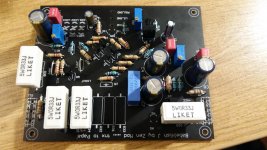

observe orientation - all LED anodes are looking at GND
Looking at schematics top row LED anodes looks other way around... could you confirm I am wrong? 🙂
Attachments

- Home
- Amplifiers
- Pass Labs
- About possible Babelfish J interest