as I'm always saying ...... invest most in efficient and sensitive speakers , then you need to invest less in copper and aluminium and caps .......
🙂
🙂
Dear ZM,
mmh, all my programs say the cdr file ist defective (on my Mac). Can you provide it me again and / or if possible as hpgl, thanks!
Attachments
should I post this in dedicated thread ?
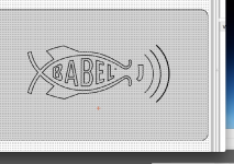
another shameless Babelfishing ?

Interesting schematic.

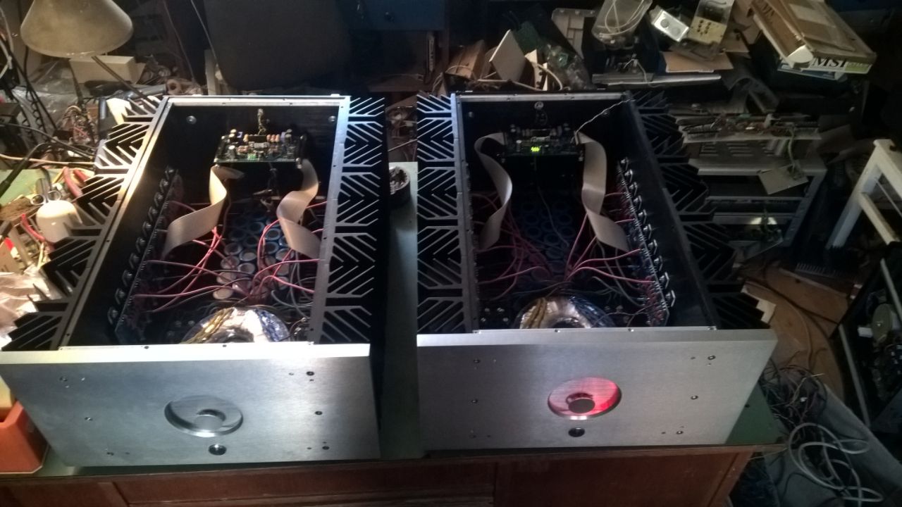
The first channel is done and ready to start up. The second is only about 4 hours behind, just need to wire in the FE board.
I made the changes required by the revised schematic for my build. And set TP2/R10 to 33R.
I had to enlarge the holes in the board due to switch to BD140’s. For double piggybacking Q1 and Q6 one pair is above board, one pair below board. I soldered the ones below board and left the leads sick through about 6mm’s then wrapped the legs from the above board pair and soldered them.


Then wired up the FE board to the rest of the amplifier. The wiring looks a little sloppy. I should have originally switched the (+) (-) power supply and I would have had less crossing wires.
A little creative wiring to accommodate 2 daughter boards.

Tomorrow I’m going to try and start the first one up. Let me know if you see any errors.
I made the changes required by the revised schematic for my build. And set TP2/R10 to 33R.
I had to enlarge the holes in the board due to switch to BD140’s. For double piggybacking Q1 and Q6 one pair is above board, one pair below board. I soldered the ones below board and left the leads sick through about 6mm’s then wrapped the legs from the above board pair and soldered them.
Then wired up the FE board to the rest of the amplifier. The wiring looks a little sloppy. I should have originally switched the (+) (-) power supply and I would have had less crossing wires.
A little creative wiring to accommodate 2 daughter boards.
Tomorrow I’m going to try and start the first one up. Let me know if you see any errors.

The first ......
you can unwrap coat from BD140s
no real benefit and just looking ugly

you can unwrap coat from BD140s
no real benefit and just looking ugly
Ok, naked they go! Thanks
Is start up the same for my version? From your post #49;
“power up ;
if green LEDs are lit , that means two things - you mount them all as needed..... and there is proper biasing voltage for LTP cascodes
- check voltage across R11 - set 10V there with TP2 and we'll have 10mA through input LTP CHANGED FOR MY VERSION to 9V4
-check voltage across R29 ; 540mV will inform as of 2A Iq ; use less if you want ; correct with TP3 if needed
- check voltage at output node - chase 0V ( up to 30mV is OK , + or - , irrelevant) , correct with TP1
last two steps are somewhat inter-dependable ; repeat them iteratively until you get desired Iq and zero offset
of course , last two steps are also dependable of open lid/closed lid situation, but you already know that final setting must be made in temperature equilibrium state , where closed lid is normal thing”
What would you think is the high limit to heat sink temperature?
Thanks for your comments!
heatsink - as always , Papa's palm rule ...... even if you cheat and instead of palm use some laser or not laser gadget
Important!
you need to decide what sum Iq is going to be ...... with multiple pairs in output , it's pretty much insane going to 2A per vertical pair and I;m sure that I wrote that somewhere in thread
what is rails voltage and what is your goal for output power ?
even if those figures are necessary to decide prior to purchasing donuts and cans and sinks , I'm asking now ....... to prevent gray smoke
Attachments
Thanks ZM!
Unloaded, I have 52v feeding the daughter boards. The transformer is 38v, 1500va.
Was hoping for 150 wpc. Possible?
Thanks

Unloaded, I have 52v feeding the daughter boards. The transformer is 38v, 1500va.
Was hoping for 150 wpc. Possible?
Thanks
150W/ch
well ....... install nice fat wirebridge on main pcb , on speaker route
think trice about gauge of wires ...... can't be sure in reference I can get from pictures, but they look tiny for amount of ambition ..... 🙂
I hope , when you are talking about 38Vac/52Vdc , that you're talking about twice that ... (+/-)
will be back soon with figures
ZM thanks as always!
Using your references Thick = 14ga, Medium = 16/18 ga, Thin = 24ga
I don’t need 150wpc per se, what do you recommend for what I have?
Using your references Thick = 14ga, Medium = 16/18 ga, Thin = 24ga
I don’t need 150wpc per se, what do you recommend for what I have?
ref to sch in #315
increase R12 to 5K6 (normal metal film) , to save little piggy of poof
counting on fact that you're using source resistors of 0R27 .........
you'll end up with rails of aroundish 48V .......
to use everything of it , and still in full current envelope at 8R load , you'll need sum Iq aroundish 4A ....... that being 4A/6 per vertical pair
be sure that (R24+TP3) combo is giving you range of min 35K and upwards (start from MINIMAL value , which is giving you min Iq)
set Iq as 0A65 through vertical pair ( being 0A65 x 0R27 = 176mV across any of 0R27 resistors)
be sure to have sum value of sense resistors (those biggies parallel on main pcb ) as 0R27/12 ...... thumb of rule is value of source resistor divided with double number of vertical pairs
you'll end up with 2 x 48V x 4A of heat ... which is 384W , divided with 12 mosfets ...... means 32W each
give me heatsink arrangement pic again , just to calm my conscience 🙂
and , yes - this way you'll be close to 150W/8R ...... with plenty of greenies to frittfritt each month , for electron-bill
why don't you resort to some normal hobby , for geezers as we are - drugs , hookers, big cars .......
well ...... if you compare these two pics :
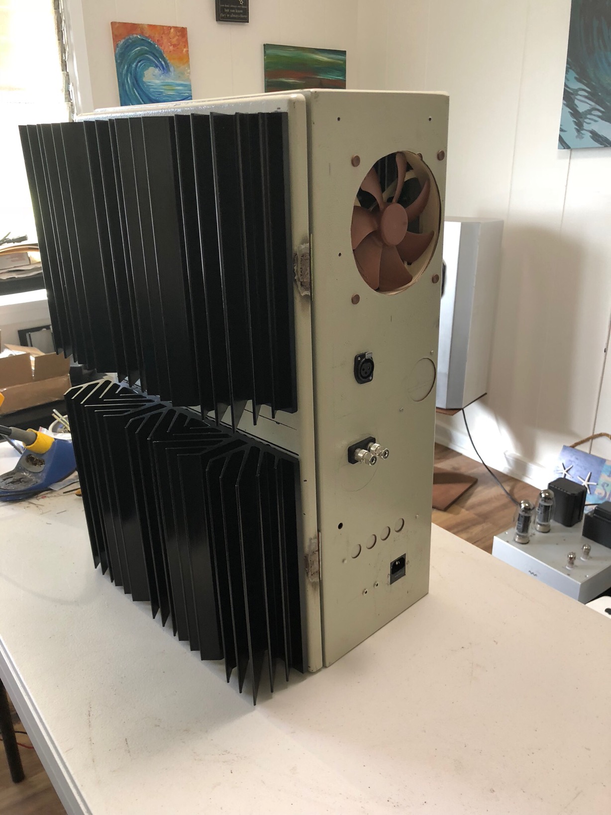
these big honking bstrds (pictured on my messy bench) are cruising with 350W of heat per case ..... and that most probably just right for summer
taking that in account ..... I believe you must go even lower , to say 300W of heat max or even lower
which means that you must go even lower with sum value of (R24+TP3) ;
if you can't decreas Iq enough , or if you see that Iq is too much wandering , you must go to increase of (R24+TP3) value and increase value of source resistors to , say , 0R47
I keep thinking that amp building would be cheaper and less troublesome than drugs, hookers and big cars? Maybe not!
Since I’m stranded on an island in the Pacific and every component change requires 4 days for new parts (without paying crazy for shipping). Can I start the first one up as is to get a feel for heat dissipation? Adjust R24+TP3 as low as possible to remain steady and monitor heat?
Does R12 need to be changed to 5K6 no matter what?
Thanks
R12 needs to be increased , to save little jfet bugger of going south
regular value is OK with regular rails , but you're in realm of Papa's ABFAB club 🙂
it stands what you intend - for R24+TP3 , monitor both heat and steadiness of Iq
regular value is OK with regular rails , but you're in realm of Papa's ABFAB club 🙂
it stands what you intend - for R24+TP3 , monitor both heat and steadiness of Iq
Great thanks!R12 needs to be increased , to save little jfet bugger of going south
regular value is OK with regular rails , but you're in realm of Papa's ABFAB club 🙂
it stands what you intend - for R24+TP3 , monitor both heat and steadiness of Iq
These are the same heat sinks that WalterW used in his Sony VFET project. In his first post, where he tested these heat sinks, his test results were 80 watts per sink. I have 5 per amp so 400 Watts diapation?
Are you using these same sinks in your monster amp? And/or did you observe different results?
Should I start with TP3 and TP1 centered or ?
TP3 at minimum , TP1 say centered
these big amps are having 350W of heat per case , that on 10pcs of heatsinks 250mm high
and that's 18 to 20C above ambient
go figure
these big amps are having 350W of heat per case , that on 10pcs of heatsinks 250mm high
and that's 18 to 20C above ambient
go figure
ZM, sorry to bother you some more, I’m so close and want to make sure I don’t make any more mistakes. I know you have a zillion other projects going.
When I originally asked about the possibility of scaling up the Babelfish J to match my existing powers supply, you provided the schematic below in post 282. This schematic shows a 45volt supply with 0R47/3w source resistors along with some other changes. This was the schematic I bought components for originally.
Can you mark up this schematic and/or confirm what would be the best final choices? Some of the latest schematic markups of earlier versions are moving closer to the one attached below.
Thanks in advance
aha
yup , problem often is my multitasking
in fact , I am the problem , due to multitasking 🙂
just confirm - you're having 0R47 resistor mounted now ?
yup , problem often is my multitasking
in fact , I am the problem , due to multitasking 🙂
just confirm - you're having 0R47 resistor mounted now ?
- Home
- Amplifiers
- Pass Labs
- About possible Babelfish J interest