Lazy ZM
see enclosed (repeated) schematic
Can you mark those resistors which have to be more than 1/2Watt type
(not writing about the 5W types)
Thank you 🙂
ZM, great and thanks for the quick reply! Too many people in my ear at work this morning. I misspoke in previous post on TP1. Yes I have installed 500R pot. Will swap for 200R as suggested.
Almost there. Thanks.
Almost there. Thanks.
Can you mark those resistors which have to be more than 1/2Watt type
(not writing about the 5W types)
Thank you 🙂
already done - that one above JFet sources - 1W
either two 2K (or even 2K2) regular metalfilms in parallel (common ones are 600mW) , or one metal oxide of 1K/1W ; these ones are same size as 600mW metalfilms , just having rougher surface , so easy to distinguish
...... Too many people in my ear at work this morning. .......
now you see how's being ZM
too many of me in my ear , constantly

Finished a couple other audio projects this week and the 200 pot came in and everything installed and pre adjusted.
I installed a slow blow 5amp fuse. Powered it up, power supply fired up, relays kicked in and the green led’s (LED 1-6) came on.
Adjusted TP2 to 20 volts across R11, but wasn't far off to begin with.
Across R29 was quickly rising past 300mV when the green leds started to blink intermittently and I could smell heat/smoke. So I quickly shut it off.
I couldn’t feel anything even warm but a residual smell seems to be coming from C11. I have clear LED’s that turn green when on. LED #3 now has a yellow/brown tint to it but no other visual clues. I double checked that the LED was installed correctly, it was, and replaced it.
Advice? Could it just be a bad LED? The way they are looped together it would seem like others would show similar discoloration if something else wrong?
C11 ?
how that can be ....... cap going south ??
there is no way that something goes wrong with LED supply , there being JFet and substantial series resistor
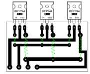
sure that you got BD140s pinout properly ?
how that can be ....... cap going south ??
there is no way that something goes wrong with LED supply , there being JFet and substantial series resistor
sure that you got BD140s pinout properly ?
C11 ?
how that can be ....... cap going south ??
there is no way that something goes wrong with LED supply , there being JFet and substantial series resistor
sure that you got BD140s pinout properly ?
Thanks for the quick response!
This is a pic of the other board in progress, but oriented same way. Both BD140’s facing same direction.

Looking back I wonder if I’m using the correct info on adjusting the pots.
I preset TP2 by adjusting the resistance across R10 and TP2 to 33ohm’s, is this correct for my build?
What should the voltage be when measured across R11 after startup?
TP3 should be 540mV across R29?
TP1 should be 0V, +/- 30mV ok?
Thanks
I preset TP2 by adjusting the resistance across R10 and TP2 to 33ohm’s, is this correct for my build?
What should the voltage be when measured across R11 after startup?
TP3 should be 540mV across R29?
TP1 should be 0V, +/- 30mV ok?
Thanks
Thanks for the quick response!
This is a pic of the other board in progress, but oriented same way. Both BD140’s facing same direction.
View attachment 666560
!!!!!!!!!!!!!!!!!!!!!!!!!!!!!!!!!!!!!
please - attach here pictures for each :
- BC556 pinout
-BD140 pinout
then write here - how you are going to solve orientation of |BD
besides writing few types in correspondence and/or in thread , even on schematic is written "TAKE CARE OF PINOUT!"
now , you must check input JFets at least with diode test (if not desoldering them and check in matching jig) , while BDs are out
check them too with diode test or Hfe or whatever , then solder them back in proper orientation
Zen Mod, you know this is your fault.
I live in a country with nanny controls on “performance” cars, fences, barriers and signs mucking up beautiful “vertically challenged scenery”, and safe places at “campuses of higher learning”.
If you really wanted me to follow "TAKE CARE OF PINOUT!", you would have written on the schematic and put exclamation marks after it (oh wait, you did!), you would have mentioned it in previous posts and messages (oh wait, you did!), well I mean if you really, really wanted me to follow these instructions instead of installing willy nilly, you should have boxed out a special square, maybe put up some flashing red lights and sent over an audio coach over to help me in this trying time!
Seriously, I don’t know what I was thinking. I actually looked up the pinout, made some notes and then I dont know what I did, no excuses, I @#%4^up!


So now I’m going to my safe place and hopefully someone there can comfort me in my distress.
OK , I admit , my fault completely!!
(simply because I'm well used to be a fool in public )
what can I say to comfort ya ......... in the end , taste of sweet victory will be even sweeter
🙂
(ZM , Master of Futile Attempts Method)
(simply because I'm well used to be a fool in public )
what can I say to comfort ya ......... in the end , taste of sweet victory will be even sweeter
🙂
(ZM , Master of Futile Attempts Method)
OK , I admit , my fault completely!!
(simply because I'm well used to be a fool in public )
what can I say to comfort ya ......... in the end , taste of sweet victory will be even sweeter
🙂
(ZM , Master of Futile Attempts Method)
I’m glad you take responsibility!😀
Because it’s runnig🎉🎉🎉🎉🎉🎉
Only issue is I’m only getting about 420mV across R29 adjusting TP3 to max
Output is zero’d out with TP1
I’ve got 20v across R11
44.6v coming into FE board

Some other observations.
Going through your startup list I didn’t short the input. I’ll try that tomorrow and see if it makes any difference.
I let it run a good 15-20 minutes, heatsinks were warming up nicely.
Adjusting TP1 and TP3 were only slightly dependent on each other as compared to adjusting my F5 v3 Turbo that was a big dance.
I performed the checks mentioned, did not find any parts fried. Compared everything to the parts on the other board that hasn’t been installed yet. Replaced C11 as it seems it smelled, and as mentioned, the one LED that looked bad.
Contorting the legs on the BD140’s was a little challenging with the previously installed shorter legs. Used a little heat shrink on the middle leg where the side leg is doing a backward flip, to be safe. BTW, how is it possible to not have had one leg in the right place? That takes talent!�� I’m going back to sniffing glue!
I’m glad you take responsibility!��
Because it’s runnig������������
Only issue is I’m only getting about 420mV across R29 adjusting TP3 to max
Output is zero’d out with TP1
I’ve got 20v across R11
44.6v coming into FE board
View attachment 666776
remind me what was a goal for Iq (voltage across source resistor)?
sorry , only way to increase it is to increase value of R24 (resistor in series with pot)
increase it exactly for pot value , that would be to 68K or 75K , back trimpot to minimum prior to powering up and repeat adjustment procedure
remind me what was a goal for Iq (voltage across source resistor)?
sorry , only way to increase it is to increase value of R24 (resistor in series with pot)
increase it exactly for pot value , that would be to 68K or 75K , back trimpot to minimum prior to powering up and repeat adjustment procedure
I’m going by your post 49;
“-check voltage across R29 ; 540mV will inform as of 2A Iq ; use less if you want ; correct with TP3 if needed
- check voltage at output node - chase 0V ( up to 30mV is OK , + or - , irrelevant) , correct with TP1
last two steps are somewhat inter-dependable ; repeat them iteratively until you get desired Iq and zero offset”
Is 540mV still a worthy goal for this build?
Thanks for your help! Can’t wait to try them out!
that is for basic build with just one pair
point me to post where I gave you specific numbers for your build
I'm kinda stretched in too many directions , so better to leave Sherlock ops to you 😉
point me to post where I gave you specific numbers for your build
I'm kinda stretched in too many directions , so better to leave Sherlock ops to you 😉
that is for basic build with just one pair
point me to post where I gave you specific numbers for your build
I'm kinda stretched in too many directions , so better to leave Sherlock ops to you 😉
Thanks ZM.
I put on my Deerstalker and went to work.
In post #369 you say it’s insane to go to 2A per vertical pair, don’t want that😀
In post #373;
“ref to sch in #315
increase R12 to 5K6 (normal metal film) , to save little piggy of poof
counting on fact that you're using source resistors of 0R27 .........
you'll end up with rails of aroundish 48V .......
to use everything of it , and still in full current envelope at 8R load , you'll need sum Iq aroundish 4A ....... that being 4A/6 per vertical pair
be sure that (R24+TP3) combo is giving you range of min 35K and upwards (start from MINIMAL value , which is giving you min Iq)
set Iq as 0A65 through vertical pair ( being 0A65 x 0R27 = 176mV across any of 0R27 resistors)
be sure to have sum value of sense resistors (those biggies parallel on main pcb ) as 0R27/12 ...... thumb of rule is value of source resistor divided with double number of vertical pairs
you'll end up with 2 x 48V x 4A of heat ... which is 384W , divided with 12 mosfets ...... means 32W each
give me heatsink arrangement pic again , just to calm my conscience
and , yes - this way you'll be close to 150W/8R ...... with plenty of greenies to frittfritt each month , for electron-bill”
But these calculation are based on a different schematic than mine (315 as noted at the beginning of this post)
I have 0R47 resistors on the FE board and 1R resistors on the Daughter boards.
Since I do not trust myself to come to proper conclusion may I wait for your reply? No hurry, I know your busy. I have a few days ahead to wait for a replacement for the fried C11 cap and to get the other amp together.
Just excited I’m this close!
So before I took the amp off my work table I thought I would see what the temp would get too in its current state. After a little over an hour it’s just a smidge over 50 degrees centigrade. As measured with my probe in a hole in the back of the heatsink. I have an internal fan, but for testing I left it off.
Being in Hawaii I sometimes forget it’s cold in a large part of the world right now. We have the windows open, a light breeze, and it’s 72 degrees (22 celsius) in the House, for reference on temp rise.

So, I don’t know, maybe this might be the right place to leave it?
Feeling good about the whole project, and since I have a small table and needed to get this amp off and complete the twin, I carried it into the living room and hooked it up. Been playing this channel for a half hour or so. Sounding good so far. But seems like I have to run the pre higher for same volume? But nothing on other channel so might be that.
Being in Hawaii I sometimes forget it’s cold in a large part of the world right now. We have the windows open, a light breeze, and it’s 72 degrees (22 celsius) in the House, for reference on temp rise.
So, I don’t know, maybe this might be the right place to leave it?
Feeling good about the whole project, and since I have a small table and needed to get this amp off and complete the twin, I carried it into the living room and hooked it up. Been playing this channel for a half hour or so. Sounding good so far. But seems like I have to run the pre higher for same volume? But nothing on other channel so might be that.
well , it seems that's it
you can do what I told you , increase those resistors an rebiasing , observing just the temp on heatsink ....... upping to 55 , but no more
let's wait for completion of second channel and some listening enjoyment , then decide what to do with Iq
you can do what I told you , increase those resistors an rebiasing , observing just the temp on heatsink ....... upping to 55 , but no more
let's wait for completion of second channel and some listening enjoyment , then decide what to do with Iq
- Home
- Amplifiers
- Pass Labs
- About possible Babelfish J interest