BDX are quite close to TIPs in terms of current gain - only lower max voltage - 80V (index A) , so rails should be max +-40, so I think they will work.
MJ 4034/31 seems closer to MJ 11015/16 ( higher gain - bat Mj11015/16 works fine). Also more heat dissipation - 200W, but again - lower voltage - 80V (TIPs = 100V). So ir will be fine with two pairs @ 40V rails.
MJ 4034/31 seems closer to MJ 11015/16 ( higher gain - bat Mj11015/16 works fine). Also more heat dissipation - 200W, but again - lower voltage - 80V (TIPs = 100V). So ir will be fine with two pairs @ 40V rails.
Hi All, Prasi CRC psu board, I cant seem to see what the value for RS" should be. And also, when using a centre tapped trafo, should all the resistors labelled R1-R6 and R1'-R6' beneath the board be populated?
Snubber resistor values need to be calculated , for eg. using the quasimodo jig from Mark Johnson : Simple, no-math transformer snubber using Quasimodo test-jigHi All, Prasi CRC psu board, I cant seem to see what the value for RS" should be. And also, when using a centre tapped trafo, should all the resistors labelled R1-R6 and R1'-R6' beneath the board be populated?
Prasi made Gerbers for PSU boards , which can be used and adapted to use on this , or any similar amplifier using dual rails , very versatile board . Compact solution for crc psu using LT4320

I just noticed that the trafo I have here is 43-0-43 before rectifier, and its the only one i have. After rectifier its going to be 60vdc per rail. Whats the max voltage I can use on this am
TIP142/147 100VdcI just noticed that the trafo I have here is 43-0-43 before rectifier, and its the only one i have. After rectifier its going to be 60vdc per rail. Whats the max voltage I can use on this am
#1 Nelson Pass:
''Rails: +/-50v or so''
I think better to keep the psu voltage below or max 50V. there is some discussion on this thread regarding whats the max voltage that can be used for different versions of TIP devices.
https://www.stereophile.com/integratedamps/780/index.htmlYou are missing something, but the details would be embarrassing to
some parties and are best left in the "no good deed goes unpunished" file,
which contains other stories about people you think you know...
Hi all,
First of all I would like to thank the prasi for the excellent pcb design.
I really like the design, as it fits into a MODUSHOP 2U box. I have two new unused TALEMA 225W 2x25V transformers at home and I want to use them for this project. The power of 50W 8Ohm is enough for me...
Do I need to adjust any values for the lower voltage of 35V 0V 35V?
How about capacitor C9 (0p) are you not planting anything at that position?
Is it also necessary to pair the output transistors to a similar hfe?
Thank You !
Hi,
for 35V rails no additional adjustments required - one of my ab100 works fine with +-38V rails.
this capacitor is needed if there is an oscillation or instability - but in practice no one has ever needed it.
No- it is not necessary.
for 35V rails no additional adjustments required - one of my ab100 works fine with +-38V rails.
this capacitor is needed if there is an oscillation or instability - but in practice no one has ever needed it.
No- it is not necessary.
On which components should we act to have a more transparent and neutral and quite lively rendering sound ? Some amps give a dull and shimmering sound which is wanted by the designer. In this, we must also be able to act on the sound of this amp?
I recall Nelson mentioning Elna Silmic 11 caps for the 100uF electrolytics .
I went for 100V version IIRC , check for correct lead space and diameter .
https://www.mouser.co.za/c/passive-...c-capacitors-radial-leaded|~Voltage Rating DC
I went for 100V version IIRC , check for correct lead space and diameter .
https://www.mouser.co.za/c/passive-...c-capacitors-radial-leaded|~Voltage Rating DC
I guess matching small input devices could help , I did do this , and matched left and right channels . For small poly caps I used Wima MKS . Resistors I used 1 percent metal film and used 1 watt in 1/2watt bodies . Drivers recommended by Prasi are excellent linear devices developed for TV , I also like using TV tubes in tube amplification , for their linearity and low input and output capacitance .
I think better to keep the psu voltage below or max 50V. there is some discussion on this thread regarding whats the max voltage that can be used for different versions of TIP devices.
Would any of the higher voltage MJH110xx devices work?
Onsemi MJH110xx Data Sheet
The devices you show look promising - be sure and select the TO-247 option, otherwise you'll have to scare up a TO-3 shoulder washer to insulate the mounting screw from the device tab.
Andrew get your self a cup of coffee and a schematic 😀
The A40 features 2X TIP142 and 2XTIP147 in the output stage that makes 4 transistors in the output that inside of them include 4 drivers ...
Sounds great, bottom end is impressive, however it won't be replacing my Aleph J clone any time soon.
Also would have to build 2nd channel and correct the errors on the board tidy it up etc.
Regards
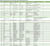
Am I the only one who missed that Prasi posted a full BOM in message 1121?
Link to Prasi AB100 BOM
Almost everything is in stock at Mouser right now, just not one 2 watt resistor and the TIP142/147.
Link to Prasi AB100 BOM
Almost everything is in stock at Mouser right now, just not one 2 watt resistor and the TIP142/147.
Attachments
- Home
- Amplifiers
- Pass Labs
- AB100 Class AB Power Amplifier