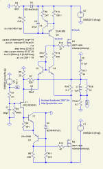
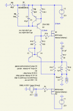
Have measured spectrum for different output power values. 5.6 Ohm resistance was used for the amplifier loading.
1. "Harmonics SPL" (i.e. levels vs frequency) curves measured with QLoud http://gaydenko.com/qloud/ are here:
http://gaydenko.com/ab-dynamic/measurement/qloud/
2d - green
3d - red
4th - light green
5th - light red
2. Spectrum curves of 1KHz signal for different power values were measured with 'jaaa' http://www.kokkinizita.net/linuxaudio/ and are here
http://gaydenko.com/ab-dynamic/measurement/spectrum1000Hz/
3. The same as 2, but for 7Hz (you can ignore QLoud results below 10Hz because sweep-sine signal starting from rather low frequency must be too long to be handy):
http://gaydenko.com/ab-dynamic/measurement/spectrum0007Hz/
At all cases you can notice measurement chain noise when output power is small. Also ignore 50Hz hum in 7Hz-results.
Among all my amps this case measurements are closest to LTspice-predicted results.
The revolution isn't done only, it is proved also! 😉
hrefs were changed
Sorry, I have reorganized files at gaydenko.com, as a result all AB-dynamic related hrefs now start with http://gaydenko.com/audio/ab-dynamic/ rather http://gaydenko.com/ab-dynamic/
Sorry, I have reorganized files at gaydenko.com, as a result all AB-dynamic related hrefs now start with http://gaydenko.com/audio/ab-dynamic/ rather http://gaydenko.com/ab-dynamic/
If you are saying about this variant, just remove R5 and replace R7,C2 with shortcut.how do i configure your amp as buffer only, no gains?
Attachments
Strictly speaking, this schematics isn't intended to be used as follower - input part design makes such using impossible: look at D2 and drain voltage of J1. As far as I don't like preamp+follower topology ("too many parts"), I didn't design follower exploring the main (dynamic load) idea.how much will be the maximum rail swing? do I need an clip protection?
cheers.
You can take this simplest follower sketch as starting point to play with. At positive half output is limited with ~ (V2 - 5V).
You can use any follower at M2 place (say bjt) - M1 and around is self-contained dynamic load.
Attachments
anli,
what a nice circuit! I would connect the junction of X1`s collector and D2 to the source of J1 instead to ground.
atiq19,
omit R7, C2, R5 and use an active current source.
what a nice circuit! I would connect the junction of X1`s collector and D2 to the source of J1 instead to ground.
atiq19,
omit R7, C2, R5 and use an active current source.
IIRC, I have looked at such variant but rejected one because of RF instability or unusual demands to J1 parameters (or both). BTW, two main demands to an amplifier itself (i.e. all without dynamic load) were simplicity and high PSRR wrt negative rail (as for positive one - it is already very high).anli,
what a nice circuit! I would connect the junction of X1`s collector and D2 to the source of J1 instead to ground.
anli,
it gives some advantages and I don`t expect any serious stability problems. To increase stability and PSRR, I would insert a base-stopper for Q1, use active CCS instead of R11, R3/R4 and lower the value of R2.
it gives some advantages and I don`t expect any serious stability problems. To increase stability and PSRR, I would insert a base-stopper for Q1, use active CCS instead of R11, R3/R4 and lower the value of R2.
As for R3,R4,R11 - agree, at first view CCS seem to be nice, but in reality we will not get any advantage in PSRR, but increase complexity.anli,
it gives some advantages and I don`t expect any serious stability problems. To increase stability and PSRR, I would insert a base-stopper for Q1, use active CCS instead of R11, R3/R4 and lower the value of R2.
As for R2 - of course, it is useful to make it as small as possible with given signal source.
I'm not familiar well with all this English slang - what is "base-stopper"?
Aha, I see - the way to explore bjt input capacitance.anli,
base-stopper=base resistor.
This gives clean voltage at the base:
Yes, there are plenty of ways to design this 'amplification ring" (J1 R8 M2 R16 R7 J1), some of them are presented in the project's directory. But I feel, if we return to music, a listening experience is defined by the dynamic load. So, at last, I have decided to keep all other parts as simple as possible (staying in DC-amp topology).
anli,
I´m not urging you to make changes in your working amp, just discussing. Again, it`s a great design, done with finesse.
I´m not urging you to make changes in your working amp, just discussing. Again, it`s a great design, done with finesse.
Lumba,anli,
I´m not urging you to make changes in your working amp, just discussing. Again, it`s a great design, done with finesse.
No-no, I don't interprete your words as urging - just try to clarify decisions were made on the way to the idea realization 🙂
Hi,
I agree with you on keeping things simple, would definitely not suggest to add another stage, for instance. Active devices are less linear, but ripple does much harm, especially at the sensitive bases and gates. Also, there are other good reasons for approaching ideal values. In battery-powered situations I would use resistors as current and voltage sources.
I agree with you on keeping things simple, would definitely not suggest to add another stage, for instance. Active devices are less linear, but ripple does much harm, especially at the sensitive bases and gates. Also, there are other good reasons for approaching ideal values. In battery-powered situations I would use resistors as current and voltage sources.
I have tried (for soldered variant) in LTspice to replace this or that R with ideal CCS (as well as zeners with ideal voltage source) and have not found noticeable PSRR increasing (and, as I have noted, for positive rail PSRR is extremely high as is).Hi,
I agree with you on keeping things simple, would definitely not suggest to add another stage, for instance. Active devices are less linear, but ripple does much harm, especially at the sensitive bases and gates. Also, there are other good reasons for approaching ideal values. In battery-powered situations I would use resistors as current and voltage sources.
It seems like there is common trend to use "near ideal" voltage or current sources (as well as, say, shunting zeners with C) without estimating of real effect in real place - just make this place "better". In practice I have met places when adding shunting C to zener decreased PSRR - yes, paradox 🙂 Sorry, don't remember that case, but strating from that point I try to avoid "let's make this place a little better" rule 😀
anli,
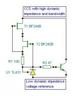
dynamic impedance values approaching the ideal (infinite for current sources, zero for voltage sources) will increase ripple rejection. See picture in post #72.
dynamic impedance values approaching the ideal (infinite for current sources, zero for voltage sources) will increase ripple rejection. See picture in post #72.
Lumba,
I'm aware about it 😉 And, as you can see, I use CCS where it is indead needed (and, BTW, that CCS, which permits to change thermo-coefficient). But, as I have noted earlier, it is obligatory to check usefulness of this or that improvement in a concrete scheme in a concrete place.
I'm aware about it 😉 And, as you can see, I use CCS where it is indead needed (and, BTW, that CCS, which permits to change thermo-coefficient). But, as I have noted earlier, it is obligatory to check usefulness of this or that improvement in a concrete scheme in a concrete place.
Hi,
Did you have problems with DC stability? How did you determine the ratio between R10 and R13?
Right.I use CCS where it is indead needed
Did you have problems with DC stability? How did you determine the ratio between R10 and R13?
- Status
- Not open for further replies.
- Home
- Amplifiers
- Solid State
- AB-dynamic


