The main first switching on is to make with the power supply of the transformer through a 100W incandescent lamp.

Only fireworks, only hardcore-)The main first switching on is to make with the power supply of the transformer through a 100W incandescent lamp.
@Topa41
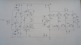
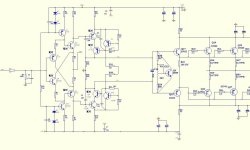
Be careful with that 669 transistor which is soldered upwards. If you plan to install the power transistors below the board, as usual, then you have to re-solder it below, so it will be on the heat sink with the output transistors. That is very important. Based on how the leads of power transistors are bent, I assume you will mount them below the board.
You are bypassing both the on-board power supply and also speaker protection. Is that just temporarry or permanent decision? It would be reasonable to use the speaker protection.
Enjoy building your amplifier!
... we love the smell of smoke over the smoldering electronics ... 😉Only fireworks, only hardcore-)

https://www.diyaudio.com/community/threads/a60-amplifier-build-this.368256/post-7280812@Topa41
Be careful with that 669 transistor which is soldered upwards. If you plan to install the power transistors below the board, as usual, then you have to re-solder it below, so it will be on the heat sink with the output transistors. That is very important. Based on how the leads of power transistors are bent, I assume you will mount them below the board.
You are bypassing both the on-board power supply and also speaker protection. Is that just temporarry or permanent decision? It would be reasonable to use the speaker protection.
Enjoy building your amplifier!
All this is there, but external. I remember about the transistor, thanks.
Hello Berlusconi. Got new boards on transistors 4281/4302? Can't wait to get your opinion on this amp.
Hello VMK,
I have tried 2SC5200/2SA1943, MJL1302/MJL3281 and MJW1302/MJW3281. I honestly can't say the difference. However, people praise 4281/4302, this could be audible.
I'm sure that this amplifier as a whole is the reason for pleasant sound, not just individual components. There are quite a lot of generic components in it from 'less reputable sources' and yet this does not degrade it. I also have tried different small transistors from reputable producer (ON Semi), but I have replaced them with CDIL transistors (India). Not because I have some regional/national preferences - they simply measure better in this particular case.
I wish you a pleasant week end, dear friend.
Something tells me if there will be an improvement, but not by much. You need to switch from Accuphace to something new.
Heĺo dear Paroxod,Let me reveal my secret project:
Class A High Power Stereo Dual Channel HiFi Audio Amplifier Board Power Tube AMP Upgrade Accuphase E405/550/KSA50
I have tested that expensive amplifier and it ended-up in the bin. Horrible product. I will never again purchase any Chinese audio product. It appears, that with A60 I was just plain lucky. A60 is just an exception. All other Chinese boards ended in the bin too. I have thrown them all together. But this A60 remains - it is really the best. Also, I have learned a lot from testing all these amplifiers which are in the bin, with all other garbage. And the EA40 was the garbage on steroids.
I wish you a pleasant weekend dear Paroxod
Berlusconi, I advised you to leave Accupface clones (except A60). The Chinese went the wrong way. We need to stop at the right time and move on. In pursuit of money and in the wake of popularity (A60 +), they began to create, frankly, rubbish. Stuffing radio components on the board and a bunch of transistors at the output does not speak of quality. Very sorry for the waste of money and time. I wish you more successful projects. I think it's not the Chinese with their products that are to blame, but the fact that they begin to be smart and design and change at their own discretion, and thereby worsen the characteristics of a deliberately normal circuit.😉
Yesterday I listened to the A60 with a preliminary KRELL at a good volume (laptop + DAC, rip to FLAC). Robert Plant (1988) sang in such a way that goosebumps ran. For those who doubt, this option (and even more so the A60 +) is quite a competitor to expensive branded amplifiers, you just need to take the right boards, power supply capacitors and output transistors. 👍
Hello Berlusconi. You mentioned CDIL transistors. Tell me which ones? I have now assembled 2 new boards, in which I myself carefully selected transistors from a large number of them. But there is no time to place them in the case yet. So I haven't listened to both channels on 4281/4302 at the same time yet. As I understand it, these transistors heat the radiator more. I hope it reflects in the sound 🙂

The people went deep into the work apparently. 😀
While the issue of anodizing radiators is being resolved, I decided to put in order and bring beauty to what had been in bare metal for many years.
While the issue of anodizing radiators is being resolved, I decided to put in order and bring beauty to what had been in bare metal for many years.
Attachments


Hi vmk2002!Hello Berlusconi. You mentioned CDIL transistors. Tell me which ones? I have now assembled 2 new boards, in which I myself carefully selected transistors from a large number of them. But there is no time to place them in the case yet. So I haven't listened to both channels on 4281/4302 at the same time yet. As I understand it, these transistors heat the radiator more. I hope it reflects in the sound 🙂
Sorry for the delayed response.
Here are my substitutes:
2SA970 -- CDIL 2SA970
2SC2240 -- CDIL 2SC2240
2SC2705 -- ISC 2SC3423
2SA1145 -- ISC 22SA1360
MJE15034 – ONS MJE15034
MJE15035 – ONS MJE15035
Output: 2sc/2sa, MJL, NJW
Please note that both CDIL and ISC (Inchange) produce quality replacements
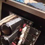
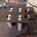
At these terminals you can measure quiescent current with multimeter.
1. Make sure you have no signal at the input.
2. Read the potential across these two points (in mV range)
3. Divide the reading by the value of the emitter resistors (usually 0.25 ohm)
The result is quiescent current in mA.
The reading should be in the range of 20 to 60 mV (! millivolts)
This value is adjusted with the multiturn resistor. Counter-clock direction increases the quiescent current. Adjust carefully with current limiter using incandescent light bulb.
Carefully, otherwise you may blow your amplifier board.
You're welcome @Topa41
Wait, before you start, there are few more important things:
Before you start anything make sure that the potentiometer is turned clockwise to the limit. Remember: clockwise. This will prevent any unpleasant surprises with surge of very high current to the output devices. When you turn the potentiometer completely clockwise, the quiescent current will be at the minimum. Measure it immediately after the first start-up.
This all must be done with current limiter.
However, the current limiter will cause that your rail voltages will sag significantly and your quiescent current must be adjusted WITHOUT the current limiter. Otherwise the adjustment would be too high for normal operation.
First adjust voltage at "Test" points to 15-20 mV, without the current limiter then observe temperatures at your output devices and increase slowly until the temperature is too high or until 60 mV. Always let temperature to stabilise before you make any further adjustments.
Good luck! 👍🙂
- Home
- Amplifiers
- Solid State
- A60(+) Amplifier. Build this?